Esp32-Cam image recognition
- 1. Web page display video stream
-
- 1. Linux-style routines
- 2. MicroPython routines
-
- Step 1. Download Thonny
- Step 2. Burn Esp32-Cam firmware
- Step 3. Run the corresponding code
- 3. Arduino-style routines
-
- Step 1. Download Arduino
- Step 2. Install the Esp32-Cam library
- Step 3. Select a routine
- Step 4. View the running results
- 2. Realize image recognition within half an hour
-
- 1. Web video streaming
- 2. Collect and train the target through the video stream
-
- Step 1. Create a new Spyder project
- Step 2. Acquisition of training data
- Step 3. Data processing and model building
- 3. Generate code and transplant it to Esp32-Cam
-
- (1) Convert HOG and RF algorithms into C++ codes that can run on Esp32-cam
- (2) Create an Arduino project project
- (3) Burn to Esp32-Cam
This project allows you to achieve model training and image recognition in half an hour, very simple.
Click here to play the effect video before starting
1. Web page displays video stream
There are many ready-made resources, as long as you search a little bit and burn the program to Esp32-Cam, you can realize this function. You can go to study for details, so I won’t go into details here.
1. Linux-style routines
You can learn the routines of Anxinke official website, which is authoritative. click to go
The tutorial is very detailed, brothers with Linux foundation can try it, otherwise don’t bother with it (such as vim editor use, shell script use, linux configuration, etc., it is very time-consuming, and few people have tried it successfully)
2. MicroPython routines
This way is to make Esp32-Cam have a python environment and be able to run py files. click to go
Step 1. Download Thonny
Download address: https://thonny.org/
Step 2, burn Esp32-Cam firmware
Using Thonny, if the boot.py file cannot be displayed after burning the firmware, then there should be a problem with the base board, and you can buy the corresponding base board specified, but in fact, use the USB to ttl, and the DuPont line should be connected to 5V, GND, TXD and RXD.
Step 3, run the corresponding code
import socket
import network
import camera
import time


# connect wifi
wlan = network.WLAN(network.STA_IF)
wlan. active(True)
if not wlan.isconnected():
    print('connecting to network...')
    wlan.connect('dongfeiqiu', 'wangmingdong1225')

    while not wlan.isconnected():
        pass
print('Network configuration:', wlan.ifconfig())


# Camera initialization
try:
    camera.init(0, format=camera.JPEG)
except Exception as e:
    camera.deinit()
    camera.init(0, format=camera.JPEG)


# other settings:
# scroll up and down
camera. flip(1)
#about
camera. mirror(1)

# resolution
camera. framesize(camera. FRAME_HVGA)
# The options are as follows:
# FRAME_96X96 FRAME_QQVGA FRAME_QCIF FRAME_HQVGA FRAME_240X240
# FRAME_QVGA FRAME_CIF FRAME_HVGA FRAME_VGA FRAME_SVGA
# FRAME_XGA FRAME_HD FRAME_SXGA FRAME_UXGA FRAME_FHD
# FRAME_P_HD FRAME_P_3MP FRAME_QXGA FRAME_QHD FRAME_WQXGA
# FRAME_P_FHD FRAME_QSXGA
# For more information, please check this link: https://bit.ly/2YOzizz

# special effects
camera.speffect(camera.EFFECT_NONE)
#Options are as follows:
# Effects\
one (default) Effects\
egative Effects\BW Effects\Red Effects\Green Effects\Blue Effects\Retro Effects
# EFFECT_NONE (default) EFFECT_NEG \EFFECT_BW\ EFFECT_RED\ EFFECT_GREEN\ EFFECT_BLUE\ EFFECT_RETRO

# white balance
# camera.whitebalance(camera.WB_HOME)
#Options are as follows:
# WB_NONE (default) WB_SUNNY WB_CLOUDY WB_OFFICE WB_HOME

# saturation
camera.saturation(0)
#-2,2 (default 0). -2 grayscale
# -2,2 (default 0). -2 grayscale

# Brightness
camera. brightness(0)
#-2,2 (default 0). 2 Brightness
# -2,2 (default 0). 2 brightness

# contrast
camera. contrast(0)
#-2,2 (default 0).2 high contrast
#-2,2 (default 0). 2 highcontrast

# quality
camera. quality(10)
#10-63 The smaller the number, the higher the quality

# Creation of socket UDP
s = socket.socket(socket.AF_INET,socket.SOCK_DGRAM,0)

try:
    while True:
        buf = camera.capture() # get image data
        s.sendto(buf, ("192.168.31.53", 9090)) # Send image data to the server
        time. sleep(0.1)
except:
    pass
finally:
    camera.deinit()

</code><img class="look-more-preCode contentImg-no-view" src="//i2.wp.com/csdnimg.cn/release/blogv2/dist/pc/img/newCodeMoreBlack.png" alt ="" title="">
3. Arduino-style routine
This is also the simplest implementation routine I found, and it has a lot of resources, and the language involved is mainly C++. click to go
Step 1. Download Arduino
Download address: click to go
Step 2, install the Esp32-Cam library
Method 1: Install in IDE.
(1). File → Preferences → Additional development board manager URL, modify the URL to
https://arduino.esp8266.com/stable/package_esp8266com_index.json
https://raw.githubusercontent.com/espressif/arduino-esp32/gh-pages/package_esp32_index.json
(2). Tools → Development Board → Development Board Manager, search esp32, click to install
Method 2: Download the zip archive from github as a library
Download address: click to go
After downloading the zip archive, project → include library → add .ZIP library
Step 3, select a routine
Tools →Development Board →esp32 →AI Thinker ESP32-CAM
Fill wifi and password in the following location
const char* ssid = "Your wifi name";
const char* password = "wifi password";
The complete code is intercepted as follows
#include "esp_camera.h"
#include <WiFi.h>

//
// WARNING!!! Make sure that you have either selected ESP32 Wrover Module,
// or another board which has PSRAM enabled
//

//Select camera model
//#define CAMERA_MODEL_WROVER_KIT
//#define CAMERA_MODEL_ESP_EYE
//#define CAMERA_MODEL_M5STACK_PSRAM
//#define CAMERA_MODEL_M5STACK_WIDE
#define CAMERA_MODEL_AI_THINKER

#include "camera_pins.h"

const char* ssid = "Your wifi name";
const char* password = "wifi password";

void startCameraServer();

void setup() {<!-- -->
  Serial.begin(115200);
  Serial. setDebugOutput(true);
  Serial. println();

  camera_config_t config;
  config.ledc_channel = LEDC_CHANNEL_0;
  config.ledc_timer = LEDC_TIMER_0;
  config.pin_d0 = Y2_GPIO_NUM;
  config.pin_d1 = Y3_GPIO_NUM;
  config.pin_d2 = Y4_GPIO_NUM;
  config.pin_d3 = Y5_GPIO_NUM;
  config.pin_d4 = Y6_GPIO_NUM;
  config.pin_d5 = Y7_GPIO_NUM;
  config.pin_d6 = Y8_GPIO_NUM;
  config.pin_d7 = Y9_GPIO_NUM;
  config.pin_xclk = XCLK_GPIO_NUM;
  config.pin_pclk = PCLK_GPIO_NUM;
  config.pin_vsync = VSYNC_GPIO_NUM;
  config.pin_href = HREF_GPIO_NUM;
  config.pin_sscb_sda = SIOD_GPIO_NUM;
  config.pin_sscb_scl = SIOC_GPIO_NUM;
  config.pin_pwdn = PWDN_GPIO_NUM;
  config.pin_reset = RESET_GPIO_NUM;
  config.xclk_freq_hz = 20000000;
  config.pixel_format = PIXFORMAT_JPEG;
  //init with high specs to pre-allocate larger buffers
  if(psramFound()){<!-- -->
    config.frame_size = FRAMESIZE_UXGA;
    config.jpeg_quality = 10;
    config.fb_count = 2;
  } else {<!-- -->
    config.frame_size = FRAMESIZE_SVGA;
    config.jpeg_quality = 12;
    config.fb_count = 1;
  }

#if defined(CAMERA_MODEL_ESP_EYE)
  pinMode(13, INPUT_PULLUP);
  pinMode(14, INPUT_PULLUP);
#endif

  // camera init
  esp_err_t err = esp_camera_init( &config);
  if (err != ESP_OK) {<!-- -->
    Serial.printf("Camera init failed with error 0x%x", err);
    return;
  }

  sensor_t * s = esp_camera_sensor_get();
  //initial sensors are flipped vertically and colors are a bit saturated
  if (s->id.PID == OV3660_PID) {<!-- -->
    s->set_vflip(s, 1);//flip it back
    s->set_brightness(s, 1);//up the blightness just a bit
    s->set_saturation(s, -2);//lower the saturation
  }
  //drop down frame size for higher initial frame rate
  s->set_framesize(s, FRAMESIZE_QVGA);

#if defined(CAMERA_MODEL_M5STACK_WIDE)
  s->set_vflip(s, 1);
  s->set_hmirror(s, 1);
#endif

  WiFi.begin(ssid, password);

  while (WiFi.status() != WL_CONNECTED) {<!-- -->
    delay(500);
    Serial. print(".");
  }
  Serial.println("");
  Serial.println("WiFi connected");

  startCameraServer();

  Serial.print("Camera Ready! Use 'http://");
  Serial.print(WiFi.localIP());
  Serial.println("' to connect");
}

void loop() {<!-- -->
  // put your main code here, to run repeatedly:
  delay(10000);
}
</code><img class="look-more-preCode contentImg-no-view" src="//i2.wp.com/csdnimg.cn/release/blogv2/dist/pc/img/newCodeMoreBlack.png" alt ="" title="">
Step 4, view the running results

Tools→Serial monitor, then press the reset button of esp32-cam

Copy the URL and open it on the webpage, you can watch the real-time content of the camera

2. Image recognition within half an hour
1. Webpage video stream
Similar to the previous Arduino example, but the included library is not the official one, but this one: Click here
After downloading the zip library, include the library in the IDE operation, and then copy the following code as a new project ino file. Note: To configure your own board, then change to your own wifi and password
#include "eloquent.h"
#include "eloquent/networking/wifi.h"
#include "eloquent/vision/camera/esp32/webserver.h"
// Replace 'm5wide' with your own module,
// Supported modules are 'aithinker', 'eye', 'm5stack', 'm5wide', 'wrover'
#include "eloquent/vision/camera/aithinker.h"//I use aithinker
void setup() {<!-- -->
    Serial.begin(115200);
    delay(2000);
    camera.jpeg();
    camera.qqvga();
    // Change to your own wifi and password
    while (!wifi. connectTo("Abc", "12345678"))
        Serial.println("Cannot connect to WiFi");
    while (!camera.begin())
        Serial.println("Cannot connect to camera");
    webServer. start();
    Serial.print("Camera web server started at http://");
    Serial.println(WiFi.localIP());
}
void loop() {<!-- -->
    // do nothing
}
</code><img class="look-more-preCode contentImg-no-view" src="//i2.wp.com/csdnimg.cn/release/blogv2/dist/pc/img/newCodeMoreBlack.png" alt ="" title="">
After compiling and burning it on the esp32-cam board, open the serial monitor, get the URL (mine is 192.168.1.103), and then open it on the webpage, which is similar to the regular Arduino video stream routine.

The video window is set so small to make the video smoother.
2. Collect and train targets through video stream
The training environment is Python, and I recommend Anaconda here
A brief introduction is: Data Visualization + JupyterNotebook + Spyder
It won’t take long to download, and then we just need to use the IDE: Spyder
After downloading, install the everywhereml package, open the Anaconda Powershell Prompt and enter the following command, already indicates that the package has been installed
pip install everywhereml>=0.2.19

Step 1, create a new Spyder project
project->new project

Then decompress the Python project for learning and training the model and add it to the project, click to get the Python project
Then open the Spyder software as shown in the figure, and the Python project will be displayed in the project file column on the left. In addition, the interactive interface and data visualization display interface are also useful.

Step 2, training data acquisition
Copy the following code to the interface and press Enter, Intercept the target picture from the video stream as the model data support
from logging import basicConfig, INFO
from everywhereml.data import ImageDataset
from everywhereml.data.collect import MjpegCollector
# Name the folder where the data will be stored
base_folder = 'Images_Data'
# The URL of the webpage displayed by the video stream
IP_ADDRESS_OF_ESP = 'http://192.168.1.103'
basicConfig(level=INFO)
try:
    image_dataset = ImageDataset.from_nested_folders(
        name='Dataset',
        base_folder=base_folder
    )
except FileNotFoundError:
    mjpeg_collector = MjpegCollector(address=IP_ADDRESS_OF_ESP)
    image_dataset = mjpeg_collector.collect_many_classes(
        dataset_name='Dataset',
        base_folder=base_folder,
        duration=30
    )
print(image_dataset)
</code><img class="look-more-preCode contentImg-no-view" src="//i2.wp.com/csdnimg.cn/release/blogv2/dist/pc/img/newCodeMoreBlack.png" alt ="" title="">
Then it will pop up to let you name the created class. I don’t recognize anything first, so name it none and press Enter, as shown in the figure below

After that, it will display a prompt to take 1272 pictures as the basis of model training, and ask whether the class is ok
INFO:root:Captured 1272 images
Is this class ok? (y|n)
Then enter y and press Enter. If it is the first time, you will be prompted to create a folder Images_Data to save data
INFO:root:creating D:\Esp_Cam\Spyder_Demo\Esp32_Cam\Images_Data folder
INFO:root:creating D:\Esp_Cam\Spyder_Demo\Esp32_Cam\Images_Data\
one folder
Which class are you going to capture? (leave empty to exit)
Open the corresponding folder and you will find that the captured image data is stored inside.

Similarly, I trained pen, napkin


If you don’t want to add it, just press Enter without typing
Which class are you going to capture? (leave empty to exit)
Are you sure you want to exit? (y|n)
Then enter y and press Enter to exit, and the trained class will be displayed at this time
ImageDataset[Dataset](num_images=3704, num_labels=3, labels=['napkin', 'none', 'pen'])
Step 3, data processing and model building
Step 2 obtained more than 1,000 pictures of tissues, pens, and blanks as data support

First gray the image
Execute in the interface
image_dataset = image_dataset.gray().uint8()
You can execute the following code in the interactive interface to preview the data processing
image_dataset.preview(samples_per_class=10, rows_per_class=2, figsize=(20, 10), cmap='gray')

Then use the oriented gradient histogram algorithm for processing
Histogram of Oriented Gradients (HOG for short), this algorithm is lightweight and very suitable for Esp32-cam.
Execute the following code in the interactive interface
from everywhereml.preprocessing.image.object_detection import HogPipeline
from everywhereml.preprocessing.image.transform import Resize
pipeline = HogPipeline(
    transforms=[
        Resize(width=40, height=30)#The resolution here will affect the processing time and the accuracy of model building, which can be adjusted by yourself
    ]
)
feature_dataset = pipeline.fit_transform(image_dataset)
feature_dataset. describe()

Then output a data set consisting of feature vectors
print(pipeline)

If you want to see the extracted feature quantity information, you can draw a pair plot (pairplot) to intuitively feel the data
feature_dataset.plot.features_pairplot(n=200, k=8)

It can be seen intuitively that the aggregation properties of these three classes (none, napkin, pen) are good, but to some extent they are mixed with each other.
Further optimization using dimensionality reduction algorithm
The dimensionality reduction algorithm used is Uniform Manifold Approximation and Projection (UMAP for short)
feature_dataset.plot.umap()

Analysis of point aggregation properties shows that the model of 1 (none) is the most ideal, while the models of 0 (napkin) and 2 (pen) are relatively poor.
In general, it can be used to characterize our data.
Finally train the classifier to complete the model building
The modeling method used is called Random Forest (RF)
from everywhereml.sklearn.ensemble import RandomForestClassifier
for i in range(10):
    clf = RandomForestClassifier(n_estimators=5, max_depth=10)
    train, test = feature_dataset. split(test_size=0.4, random_state=i)
    clf. fit(train)
    print('Score on test set: %.2f' % clf. score(test))
clf.fit(feature_dataset)
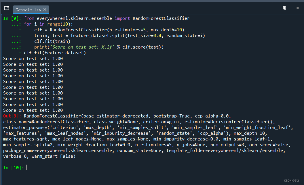
Now, we have trained and built the model
3. The generated code is ported to Esp32-Cam
(1) Convert HOG and RF algorithms to C++ code that can run on Esp32-cam
HOG algorithm to obtain feature vector data set
print(pipeline.to_arduino_file(
    filename='path-to-sketch/HogPipeline.h',
    instance_name='hog'
))
RF Algorithm Training Classifier
print(clf.to_arduino_file(
    filename='path-to-sketch/HogClassifier.h',
    instance_name='classifier',
    class_map=feature_dataset.class_map
))
At this time, two .h files will be generated in the path-to-sketch/ directory
(2) Create Arduino project
Ino file replaced with the following code
#include "eloquent.h"
#include "eloquent/print.h"
#include "eloquent/tinyml/voting/quorum.h"
// supported are 'aithinker', 'eye', 'm5stack', 'm5wide', 'wrover'
#include "eloquent/vision/camera/aithinker.h"//I use aithinker
#include "HogPipeline.h"//generated in Spyder
#include "HogClassifier.h"//generated in Spyder
Eloquent::TinyML::Voting::Quorum<7> quorum;
void setup() {<!-- -->
  Serial.begin(115200);
  delay(3000);
  Serial. println("Begin");
  camera.qqvga();
  camera. grayscale();
  while (!camera.begin())
    Serial.println("Cannot init camera");
}
void loop() {<!-- -->
  if (!camera.capture()) {<!-- -->
      Serial.println(camera.getErrorMessage());
      delay(1000);
      return;
  }
  hog. transform(camera. buffer);
  uint8_t prediction = classifier. predict(hog. features);
  int8_t stablePrediction = quorum. vote(prediction);
  if (quorum. isStable()) {<!-- -->
    eloquent::print::printf(
      Serial,
      "Stable prediction: %s \t(DSP: %d ms, Classifier: %d us)\
",
      classifier. getLabelOf(stablePrediction),
      hog. latencyInMillis(),
      classifier. latencyInMicros()
    );
  }
  camera. free();
}
</code><img class="look-more-preCode contentImg-no-view" src="//i2.wp.com/csdnimg.cn/release/blogv2/dist/pc/img/newCodeMoreBlack.png" alt ="" title="">
Find the two .h files produced earlier and include them in the project (copy the two .h files into the project)
