【Unity】Grid stroke method
This article introduces three stroke methods for the four-sided mesh of the model: including pure Shader method, mesh creation method and post-processing method. It is used to enhance the outline of the 3D model in the scene, making it more visually prominent and clear. This effect can be used to enhance objects, characters, or environments in a three-dimensional scene to make them more visually appealing.
Grid Stroke Method Resources
Shader method
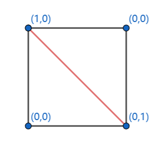
Use the GeometryShader method to calculate the triangulation network, with the purpose of retaining the two sides with the shortest distance. When performing calculations, you first need to create a float2 dist to store point information. After interpolation, you need to retain the dist of the edge, one of which is 0, and draw the edge based on this. The figure below shows the assignment of vertex dist.
This method allows us to dynamically adjust the drawing of edges based on the distance information between points when rendering the triangulation network, thereby achieving a more realistic and detailed rendering effect.
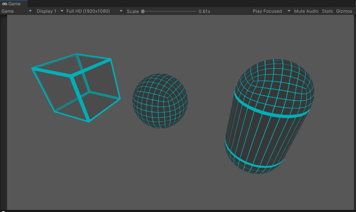
Achieve results
Implement shader
Shader "Unlit/WireframeMesh"
{<!-- -->
    Properties
    {<!-- -->
        _MainTex("Texture", 2D) = "white" {<!-- --> }
        _WireColor("WireColor", Color) = (1, 0, 0, 1)
        _FillColor("FillColor", Color) = (1, 1, 1, 1)
        _WireWidth("WireWidth", Range(0, 1)) = 1

    }
        SubShader
        {<!-- -->
            Tags {<!-- --> "RenderType" = "Transparent" "Queue" = "Transparent" }
            LOD 100
            AlphaToMask On // Enable subtractive blending for this channel
            Pass
            {<!-- -->
                Blend SrcAlpha OneMinusSrcAlpha
                Cull Off
                CGPROGRAM

                #pragma vertex vert
                #pragma geometry geom //Add geometry stage
                #pragma fragment fragment

                #include "UnityCG.cginc"

                struct appdata
                {<!-- -->
                    float4 vertex: POSITION;
                    float2 uv: TEXCOORD0;
                };

                struct v2g
                {<!-- -->
                    float2 uv: TEXCOORD0;
                    float4 vertex: SV_POSITION;
                };

                struct g2f
                {<!-- -->
                    float2 uv: TEXCOORD0;
                    float4 vertex: SV_POSITION;
                    float2 dist: TEXCOORD1;
                    float maxlenght : TEXCOORD2;
                };

                sampler2D _MainTex;
                float4 _MainTex_ST;

                float4 _FillColor, _WireColor;
                float _WireWidth, _Clip, _Lerp, _WireLerpWidth;
//viewport to geometry
                v2g vert(appdata v)
                {<!-- -->
                    v2g o;
                    o.vertex = v.vertex;
                    o.uv = TRANSFORM_TEX(v.uv, _MainTex);
                    return o;
                }
//Geometry to fragment
                [maxvertexcount(3)]
                void geom(triangle v2g IN[3], inout TriangleStream < g2f > triStream)
                {<!-- -->
                    //Read each vertex of the triangulation network
                    float3 p0 = IN[0].vertex;
                    float3 p1 = IN[1].vertex;
                    float3 p2 = IN[2].vertex;
//Calculate the length of each side of the triangular network
                    float v0 = length(p1 - p2);
                    float v1 = length( p2 - p0);
                    float v2 = length( p0 - p1);
//Find the longest side
                    float v_max = max(v2,max(v0, v1));
//Subtract the longest side from each side. When it is less than 0, it is 0, and when it is equal to 0, it is 1.
                    float f0 = step(0, v0 - v_max);
                    float f1 = step(0, v1 - v_max);
                    float f2 = step(0, v2 - v_max);

                    //Assign the value to the fragment operation
                    g2f OUT;
                    OUT.vertex = UnityObjectToClipPos(IN[0].vertex);
                    OUT.uv = IN[0].uv;
                    OUT.maxlenght = v_max;

                    OUT.dist = float2(f1, f2);
                    triStream.Append(OUT);

                    OUT.vertex = UnityObjectToClipPos( IN[1].vertex);
                    OUT.uv = IN[1].uv;
                    OUT.maxlenght = v_max;
                    OUT.dist = float2(f2, f0);
                    triStream.Append(OUT);

                    OUT.vertex = UnityObjectToClipPos( IN[2].vertex);
                    OUT.maxlenght = v_max;
                    OUT.uv = IN[2].uv;
                    OUT.dist = float2(f0, f1);
                    triStream.Append(OUT);
                }
//piece stage
                fixed4 frag(g2f i) : SV_Target
                {<!-- -->
                    fixed4 col = tex2D(_MainTex, i.uv );
                    fixed4 col_Wire= col* _FillColor;
                    //Get the minimum value of dist
                    float d = min(i.dist.x, i.dist.y);
                    //d is less than the line width, the line color is assigned, otherwise the background color is assigned
                    col_Wire = d < _WireWidth ? _WireColor : col_Wire;
                    fixed4 col_Tex = tex2D(_MainTex, i.uv);
                    return col_Wire;
                }
                ENDCG

            }
        }
}
This method does not support webGL because webGL does not support GeometryShader.
Introducing a method of creating a mesh based on uv. Although webGL is supported, it has too many limitations. I will not introduce it in detail. I will attach the shader.
Shader "Unlit/WireframeUV"
{<!-- -->
    Properties
    {<!-- -->
        _MainTex ("Texture", 2D) = "white" {<!-- -->}
        _FillColor("FillColor", Color) = (1, 1, 1, 1)
       [HDR] _WireColor("WireColor", Color) = (1, 0, 0, 1)
        _WireWidth("WireWidth", Range(0, 1)) = 1
    }
    SubShader
    {<!-- -->
        Tags {<!-- --> "RenderType"="Opaque" }
        LOD 100
        AlphaToMaskOn
        Pass
        {<!-- -->
             Tags {<!-- --> "RenderType" = "TransparentCutout" }
            Blend SrcAlpha OneMinusSrcAlpha
            Cull Off
            CGPROGRAM

            #pragma vertex vert
            #pragma fragment fragment

            #include "UnityCG.cginc"

            struct appdata
            {<!-- -->
                float4 vertex : POSITION;
                float2 uv : TEXCOORD0;
            };

            struct v2f
            {<!-- -->
                float2 uv : TEXCOORD0;
                float4 vertex : SV_POSITION;
            };

            sampler2D _MainTex;
            float4 _MainTex_ST;
            fixed4 _FillColor;
            fixed4 _WireColor;
            float _WireWidth;


            v2f vert (appdata v)
            {<!-- -->
                v2f o;
                o.vertex = UnityObjectToClipPos(v.vertex);
                o.uv = TRANSFORM_TEX(v.uv, _MainTex);
                return o;
            }

            fixed4 frag (v2f i) : SV_Target
            {<!-- -->
                fixed4 col = tex2D(_MainTex, i.uv);
                fixed2 uv2 = abs(i.uv - fixed2(0.5f, 0.5f));
                float minUV = max(uv2.x, uv2.y);
                col = minUV < 0.5- _WireWidth ? col* _FillColor : _WireColor;
                return col;
            }
            ENDCG
        }
    }
}
Create Grid Method
This method supports use in the built-in pipeline. The implementation principle is similar to the shader method, except that a line grid needs to be constructed. Extract the shortest two lines from the original triangular grid and redraw them.
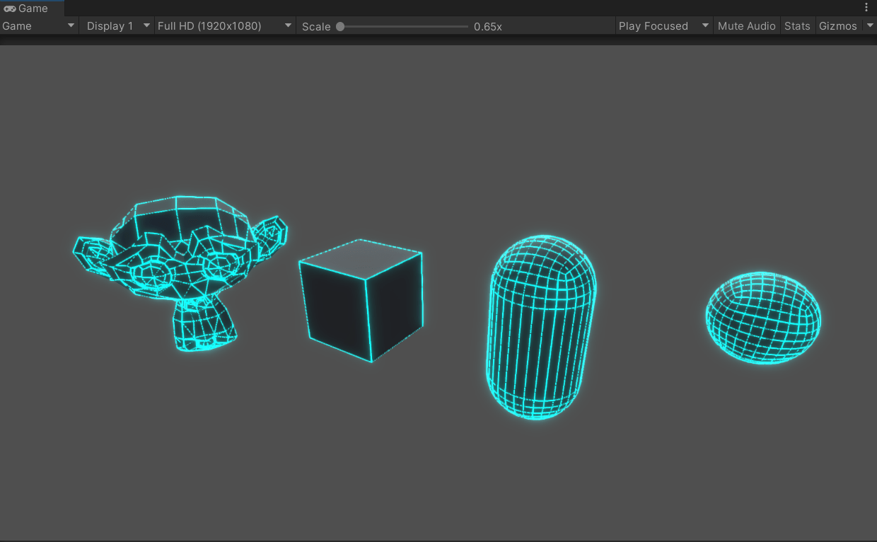
Achieve results
Because the CommandBuffer method cannot set the line width temporarily, some post-processing methods are used
Methods of implementation
using System.Collections.Generic;
using UnityEngine;
using UnityEngine.Rendering;

public class CamerDrawMeshDemo : MonoBehaviour
{
    [SerializeField]
    MeshFilter meshFilter;
    CommandBuffer cmdBuffer;
    [SerializeField]
    Material cmdMat1;

    // Start is called before the first frame update
    void Start()
    {
        //Create a CommandBuffer
        cmdBuffer = new CommandBuffer() { name = "CameraCmdBuffer" };
        Camera.main.AddCommandBuffer(CameraEvent.AfterForwardOpaque, cmdBuffer);
        DarwMesh();
    }
    //Draw the grid
    void DarwMesh()
    {
        cmdBuffer.Clear();
        Mesh m_grid0Mesh = meshFilter.mesh; //Read the original mesh. Here you need to enable the mesh to be read and write.
        cmdBuffer.DrawMesh(CreateGridMesh(m_grid0Mesh), Matrix4x4.identity, cmdMat1);
    }
    //Create grid
    Mesh CreateGridMesh(Mesh TargetMesh)
    {

        Vector3[] vectors= getNewVec(TargetMesh.vertices);
        //Convert model coordinates to world coordinates
        Vector3[] getNewVec(Vector3[] curVec)
        {
            int count = curVec.Length;
            Vector3[] vec = new Vector3[count];
            for (int i = 0; i < count; i + + )
            {
                //Coordinate transformation, multiplied by the change matrix
                vec[i] =(Vector3)(transform.localToWorldMatrix* curVec[i]) + transform.position;
            }
            return vec;
        }
        int[] triangles = TargetMesh.triangles;
        List<int> indicesList = new List<int>(2);
        //Filter drawing edges
        for (int i = 0; i < triangles.Length; i + =3)
        {
            Vector3vec;
            int a = triangles[i];
            int b = triangles[i + 1];
            int c = triangles[i + 2];
            vec.x = Vector3.Distance(vectors[a], vectors[b]);
            vec.y = Vector3.Distance(vectors[b], vectors[c]);
            vec.z = Vector3.Distance(vectors[c], vectors[a]);
            addList(vec, a,b,c);
        }
        void addList(Vector3 vec,int a,int b,int c)
        {
            if (vec.x< vec.y|| vec.x <vec.z)
            {
                indicesList.Add(a);
                indicesList.Add(b);
            }
            if (vec.y < vec.x || vec.y < vec.z)
            {
                indicesList.Add(b);
                indicesList.Add(c);
            }
            if (vec.z < vec.x || vec.z < vec.y)
            {
                indicesList.Add(c);
                indicesList.Add(a);
            }
        }
        int[] indices = indicesList.ToArray();
        //Create grid
        Mesh mesh = new Mesh();
        mesh.name = "Grid ";
        mesh.vertices = vectors;
        mesh.SetIndices(indices, MeshTopology.Lines, 0);
        return mesh;
    }
}
Post-processing methods
Depth texture and normal texture are used to compare the similarity between adjacent pixels to determine whether they are located on the edge of the object, and then achieve the stroke effect. Specifically, the algorithm compares the depth and normal values of adjacent pixels, and if the difference between them exceeds a certain threshold, the two pixels are considered to be on the edge of the object. With this method, we can perform special processing on the edges during rendering to achieve a stroke effect.
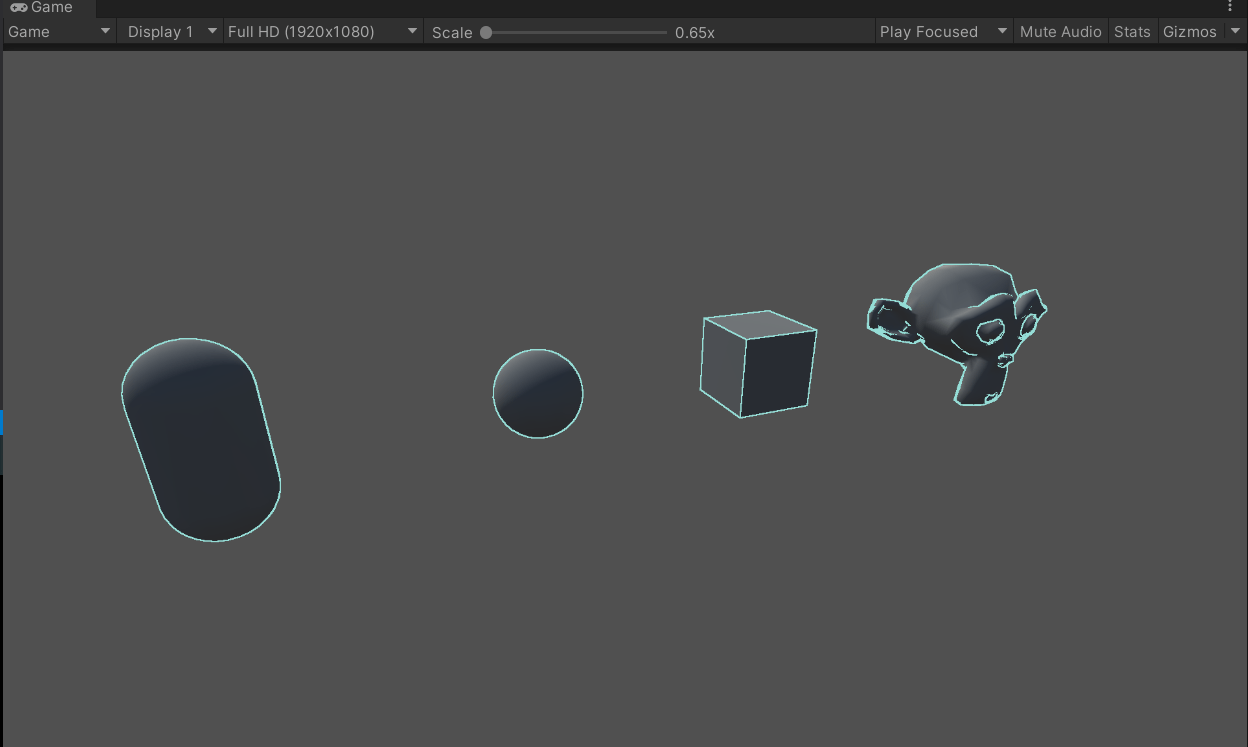
Achieve results
Implementation method
After creation, the rendering script is mounted on the main camera
using System.Collections;
using System.Collections.Generic;
using UnityEngine;

public class SceneOnlineDemo : MonoBehaviour
{
   public Shader OnlineShader;
    Material material;
    [ColorUsage(true, true)]
    public Color ColorLine;
    public Vector2 vector;
    public float LineWide;
    // Start is called before the first frame update
    void Start()
    {
        material = new Material(OnlineShader);

        GetComponent<Camera>().depthTextureMode |= DepthTextureMode.DepthNormals;
    }

    void Update()
    {

    }
    void OnRenderImage(RenderTexture src, RenderTexture dest)
    {
        if (material != null)
        {
            material.SetVector("_ColorLine", ColorLine);
            material.SetVector("_Sensitivity", vector);
            material.SetFloat("_SampleDistance", LineWide);
            Graphics.Blit(src, dest, material);
        }
        else
        {
            Graphics.Blit(src, dest);
        }
    }
}
The post-processing shader is mounted on the SceneOnlineDemo script
Shader "Unlit/SceneOnlineShader"
{
    Properties
    {
        _MainTex ("Texture", 2D) = "white" {}
      [HDR] _ColorLine("ColorLine", Color) = (1,1,1,1) //Color, usually fixed4
        _Sensitivity("Sensitivity", Vector) = (1, 1, 1, 1) //xy components correspond to the detection sensitivity of normal and depth respectively, and the zw component has no practical use
        _SampleDistance("Sample Distance", Float) = 1.0
    }
        SubShader
    {
        Tags { "RenderType" = "Opaque" }
        LOD 100

        Pass
        {
            ZTest Always Cull Off ZWrite Off

            CGPROGRAM
            #pragma vertex vert
            #pragma fragment fragment


            #include "UnityCG.cginc"

            sampler2D _MainTex;
            half4 _MainTex_TexelSize;
            sampler2D _CameraDepthNormalsTexture; //Depth + normal texture
            sampler2D _CameraDepthTexture;
            fixed4 _ColorLine;
            float _SampleDistance;
            half4 _Sensitivity;

            struct v2f
            {
                half2 uv[5]: TEXCOORD0;
                float4 vertex : SV_POSITION;
            };

            v2f vert (appdata_img v)
            {
                v2f o;
                o.vertex = UnityObjectToClipPos(v.vertex);
                half2 uv = v.texcoord;
                o.uv[0] = uv;
                #if UNITY_UV_STARTS_AT_TOP
                if (_MainTex_TexelSize.y < 0)
                    uv.y = 1 - uv.y;
                #endif
                //Create an array of adjacent vectors
                o.uv[1] = uv + _MainTex_TexelSize.xy * half2(1, 1) * _SampleDistance;
                o.uv[2] = uv + _MainTex_TexelSize.xy * half2(-1, -1) * _SampleDistance;
                o.uv[3] = uv + _MainTex_TexelSize.xy * half2(-1, 1) * _SampleDistance;
                o.uv[4] = uv + _MainTex_TexelSize.xy * half2(1, -1) * _SampleDistance;
                return o;
            }
            //Check if they are similar
            half CheckSame(half4 center, half4 sample) {
                half2 centerNormal = center.xy;
                float centerDepth = DecodeFloatRG(center.zw);
                half2 sampleNormal = sample.xy;
                float sampleDepth = DecodeFloatRG(sample.zw);

                //Normal difference
                half2 diffNormal = abs(centerNormal - sampleNormal) * _Sensitivity.x;
                int isSameNormal = (diffNormal.x + diffNormal.y) < 0.1;
                // Depth difference
                float diffDepth = abs(centerDepth - sampleDepth) * _Sensitivity.y;
                // Threshold required to scale by distance
                int isSameDepth = diffDepth < 0.1 * centerDepth;

                // return:
                // 1 - if normal and depth are similar enough
                // 0 - opposite
                return isSameNormal * isSameDepth ? 1.0 : 0.0;
            }
            fixed4 frag (v2f i) : SV_Target
            {
                    fixed4 col = tex2D(_MainTex, i.uv[0]);
                    half4 sample1 = tex2D(_CameraDepthNormalsTexture, i.uv[1]);
                    half4 sample2 = tex2D(_CameraDepthNormalsTexture, i.uv[2]);
                    half4 sample3 = tex2D(_CameraDepthNormalsTexture, i.uv[3]);
                    half4 sample4 = tex2D(_CameraDepthNormalsTexture, i.uv[4]);
                    half edge = 1.0;
                    edge *= CheckSame(sample1, sample2);
                    edge *= CheckSame(sample3, sample4);
                    fixed4 withEdgeColor = lerp(_ColorLine, col, edge);


                 return withEdgeColor;
            }
            ENDCG
        }
    }
}