1 Introduction
After studying the codes of the masters, combined with the arduino VL53L0X driver provided by the merchant when purchasing the module, I modified the ardiuno driver and wrote a VL53L0X driver compatible with C51. The microcontroller I tested is STC8H3K64S4, and the IIC communication uses the IIC of STC hardware. You only need to modify my IIC driver and display code to your own, and finally add a 1ms timer as the time base of VL53L0X, and you can use it directly.
This is my first time posting, and the work I did is relatively simple. Please forgive me if I did something wrong.
Reference websites:
Microcontroller driver for VL53L0X laser ranging module – 51 microcontroller
The program written using the code from the website above has only the most basic ranging function, and the ranging error is about ±5%. It inspired me a lot when I first came into contact with VL53L0X.
After using the VL53L0X driver for arduino provided by the merchant, the accuracy can reach ±1% due to the setting of the relevant registers of VL53L0X. Of course, the accuracy will still be much worse than the 1.2m ranging range of the module.
2. Upload the code
Main function main.c
Just replace the relevant code for human-computer interaction with your own.
void main()
{
unsigned int temp;
unsigned char high;
//Initialization
gpio();
Timer2_Init(); //Initialize timer, used for sensor time base
UartInit(); //Initialize the serial port, used to display sensor results
P16 = 0; //LED of my development board
EA = 1;
IIC_Init(); //Initialize IIC, using STC's hardware IIC
\t
\t

VL53L0X_Init(0); //Initialize the related function register area of VL53L0X
setTimeout(500); //Set timeout time 500ms
\t
//Mode selection
//#define LONG_RANGE
//#define HIGH_ACCURACY
#define HIGHT_SPEED
\t
//Related API settings for long-distance ranging
#if defined LONG_RANGE
  // lower the return signal rate limit (default is 0.25 MCPS)
  VL53L0X_setSignalRateLimit(0.1);
  // increase laser pulse periods (defaults are 14 and 10 PCLKs)
  VL53L0X_setVcselPulsePeriod(0, 18);
  VL53L0X_setVcselPulsePeriod(1, 14);
#endif

//Related API settings for high-speed ranging
#if definedHIGH_SPEED
// reduce timing budget to 20 ms (default is about 33 ms)
VL53L0X_setMeasurementTimingBudget(20000);
//Related API settings for high-precision ranging
#elif definedHIGH_ACCURACY
// increase timing budget to 200 ms
VL53L0X_setMeasurementTimingBudget(200000);
#endif
\t
while(1)
{
//Read the data of VL53L0X once
temp = VL53L0X_readRangeSingleMillimeters();
\t\t
//Can be modified according to your own display module
//Send the distance result to the serial port
//Convert to ASCLL code
Uart_Send("Distance is " ,12);
high = 0x30 + temp / 10000;
Uart_Send( & amp;high ,1);
high = 0x30 + temp % 10000 / 1000;
Uart_Send( & amp;high ,1);
high = 0x30 + temp % 1000 / 100;
Uart_Send( & amp;high ,1);
high = 0x30 + temp % 100 / 10;
Uart_Send( & amp;high ,1);
high = 0x30 + temp % 10;
Uart_Send( & amp;high ,1);
Uart_Send("mm" ,2);
//Capture the timeout of VL53L0X
if(VL53L0X_timeoutOccurred())
Uart_Send("Timeout", 7);
Uart_Send("\r\
", 2);
}
}

void Uart1() interrupt 4
{
if(RI)
RI = 0;
}
VL53L0X driver VL53L0X.c
There are too many codes, so only part of them is shown. See the attachment for details. Just remember to add a time base when you use it.
// Most of the functionality of this library is based on the VL53L0X API
// provided by ST (STSW-IMG005), and some of the explanatory comments are quoted
// or paraphrased from the API source code, API user manual (UM2039), and the
// VL53L0X datasheet.

#include "inc/VL53L0X.h"
#include "inc/VL53L0X_IIC.h"
#include "NodeHandler.h"
#include <string.h>


unsigned char stop_variable;
unsigned long measurement_timing_budget_us;
unsigned int io_timeout = 0, timeout_start_ms, t2;
bit did_timeout;


//====================================
//Your own timer time base is set to 1ms
void Time2() interrupt 12
{
t2 + + ;
}
//================================================ ==


// Defines /

// The Arduino two-wire interface uses a 7-bit number for the address,
// and sets the last bit correctly based on reads and writes
#define ADDRESS_DEFAULT 0x52

// Record the current time to check an upcoming timeout against
#define startTimeout() (timeout_start_ms = t2)

// Check if timeout is enabled (set to nonzero value) and has expired
#define checkTimeoutExpired() (io_timeout > 0 & amp; & amp; ((unsigned int)t2 - timeout_start_ms) > io_timeout)

// Decode VCSEL (vertical cavity surface emitting laser) pulse period in PCLKs
// from register value
// based on VL53L0X_decode_vcsel_period()
#define decodeVcselPeriod(reg_val) (((reg_val) + 1) << 1)

// Encode VCSEL pulse period register value from period in PCLKs
// based on VL53L0X_encode_vcsel_period()
#define encodeVcselPeriod(period_pclks) (((period_pclks) >> 1) - 1)
IIC driver
Some people like analog IIC, and some people like hardware IIC. They each have their own advantages. You can just replace and adjust my IIC driver according to your own preferences.
#define VL53L0X_address 0x52

//IIC writes 8-bit data
void VL53L0X_Write(unsigned char address, unsigned char value)
{
P_SW2 = 0xB0;
Start();
SendData(VL53L0X_address);
RecvACK();
SendData(address);
RecvACK();
SendData(value);
RecvACK();
Stop();
Delay();
P_SW2 = 0x00;
}

//IIC writes 16-bit data
void VL53L0X_Write16Bit(unsigned char address, unsigned int value)
{
P_SW2 = 0xB0;
VL53L0X_Write(address + + , (value >> 8) & amp; 0xFF);
VL53L0X_Write(address + + , value & amp; 0xFF);
P_SW2 = 0x00;
}

//IIC writes 32-bit data
//void VL53L0X_Write32Bit(unsigned char address, unsigned long value)
//{
// Start();
// SendData(VL53L0X_address);
// RecvACK();
// SendData(address);
// RecvACK();
// SendData((value >> 24) & amp; 0xFF);
// RecvACK();
// SendData((value >> 16) & amp; 0xFF);
// RecvACK();
// SendData((value >> 8) & amp; 0xFF);
// RecvACK();
// SendData(value & amp; 0xFF);
// RecvACK();
// Stop();
//Delay();
//}

//Write multi-bit data
void VL53L0X_WriteMulti(unsigned char address, unsigned char const * src, unsigned char count)
{
P_SW2 = 0xB0;
while(count--)
{
VL53L0X_Write(address + + , *(src + + ));
}
P_SW2 = 0x00;
}

//IIC reads 8-bit data
unsigned char VL53L0X_Read(unsigned char address)
{
unsigned char receive;
P_SW2 = 0xB0;
Start();
SendData(VL53L0X_address);
RecvACK();
SendData(address);
RecvACK();
\t
Start();
SendData(VL53L0X_address + 1);
RecvACK();
receive = RecvData();
SendNAK();
Stop();
Delay();
P_SW2 = 0x00;
\t
return receive;
}

//IIC reads 16-bit data
unsigned int VL53L0X_Read16Bit(unsigned char address)
{
unsigned int receive;
P_SW2 = 0xB0;
receive = VL53L0X_Read(address + + ) << 8;
receive |= VL53L0X_Read(address);
P_SW2 = 0x00;
\t
return receive;
}

//IIC reads multi-bit data
void VL53L0X_ReadMulti(unsigned char address, unsigned char * dst, unsigned char count)
{
while(count--)
{
*(dst + + ) = VL53L0X_Read(address + + );
}
P_SW2 = 0x00;
}
3.Others
Let me talk about a problem I encountered in IIC programming. When I continuously read SDA data in IIC, sometimes the data I read is unstable.
When reading continuously, read two bytes as follows
//IIC reads 16-bit data
unsigned int VL53L0X_Read16Bit(unsigned char address)
{
unsigned int receive;
IICStart();
IICSendData(VL53L0X_address);
IICWaitACK();
IICSendData(address);
IICWaitACK();
IICStop();
\t
IICStart();
IICSendData(VL53L0X_address + 1);
IICWaitACK();

    //The internal register index of VL53L0X will increase by 1 after reading a register.
receive = IICRecvData() << 8;
IICSendACK(1);
    //Read the data of the next register after adding 1 to the index
receive |= IICRecvData();
IICSendACK(0);

IICStop();
\t
return receive;
}
The internal register index of VL53L0X will increase by 1 after reading a register, and the index will increase by 1 after reading the data of the next register.
So what if the self-increasing speed of this index that increases by 1 cannot keep up with the speed of your IIC reading.
In this way, the data read by IIC will be unreliable.
After reading two bytes in a row, I modified it to read one byte twice in a row, and the data reading became much more stable.
//IIC reads 16-bit data
unsigned int VL53L0X_Read16Bit(unsigned char address)
{
unsigned int receive;
P_SW2 = 0xB0;
receive = VL53L0X_Read(address + + ) << 8; //Read one byte twice in a row
receive |= VL53L0X_Read(address);
P_SW2 = 0x00;
\t
return receive;
}
Or if you have better insights, you can tell me. After all, I have just started studying IIC, and my understanding of IIC may be wrong (maybe my program is built on BUG XD)
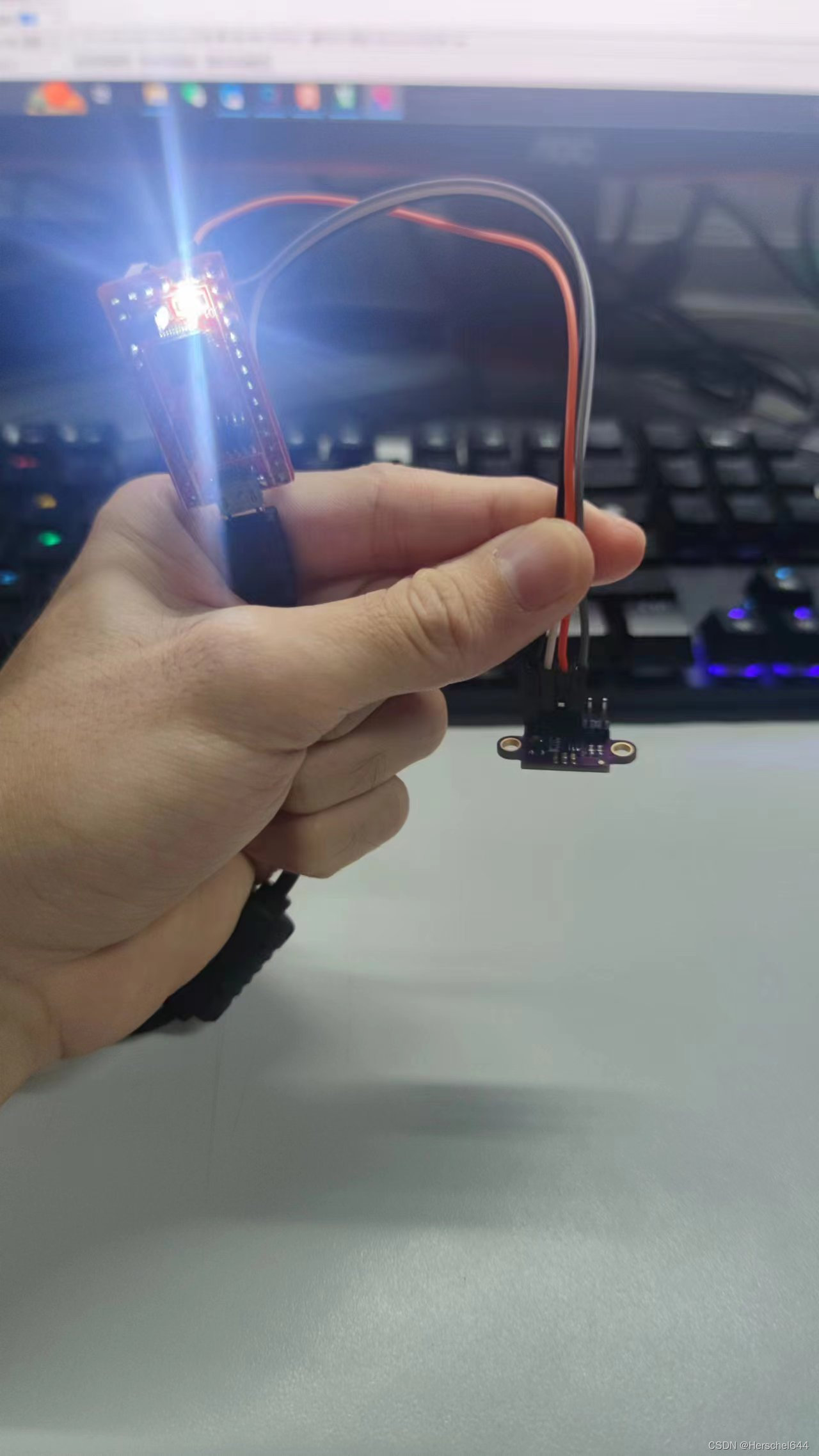
4.Results

5. Project source code and attachments
Link: https://pan.baidu.com/s/1w-9VU3cBssHT22YotEhmUg
Extraction code: hkvx
I also wrote an article on the 51 Black Electronics Forum, but due to editing problems, there was a problem with the original post display, so I came to csdn and wrote another article.