Table of Contents
1. Pin interface description diagram
2. Use of modules
1. First we initialize the module
Define busy detection function
Module initialization
2.Transmission of data
3. Determine the character display position
4. Integration of code
In this article we use LCD1602 to display a line of characters

1. Pin interface description diagram

No.
1
Feet
: VSS
for power ground
Connect to GND
No.
2
Feet
:VDD
catch
5V
positive power supply
Connect to 5V
No.
3
Feet
:VL
Contrast adjustment terminal for LCD monitor
,
The contrast is the weakest when connected to the positive power supply, and the contrast is highest when connected to the ground.
If it is too high, “ghosting” will occur.
”
, when using it, you can pass a
10K
The potentiometer adjusts the contrast.
No.
4
Feet
:
RS
For register selection, the data register is selected when the high level is high, and the instruction register is selected when the low level is low.
No.
5
Feet
:
R/W
It is a read and write signal line. When the level is high, the reading operation is performed, and when the level is low, the writing operation is performed.
When RS and
R/W
common to low level can
write command
or display address
When RS is low level R/W
can be high when
Read busy signal
,
When RS is high level
R/W
is low when the
data input
.
No.
6
Feet
:
E
terminal is the enabling terminal, when
E
When the terminal jumps from high level to low level, the liquid crystal module
Excuting an order
.
No.
7
~
14
Feet
:
D0
~
D7
for
8
bit bidirectional data lines.
No.
15
Pin: Backlight positive terminal.
Connect to 5V
No.
16
Pin: Negative pole of backlight.
Connect to GND
2. Use of modules
We want LCD1602 to display characters. In fact, we need to initialize LCD1602 first, and then tell it where to display characters (write address command) and what content to display (write data);
1. First we initialize the module

According to the module manual, we can understand the steps of module initialization, but we can see that 4. We are required to detect the busy signal every time we write instructions, read and write data operations.
So we need to detect the busy signal first, so how to detect the busy signal?
We can see that there is a sentence in the description of the pin interface above:
When RS is low level R/W
can be high when
Read busy signal
Then follow the LCD1602 module control instruction list


From instruction 9 we can see that we only need to detect the high and low bits of BF.
LCD1602 read timing diagram

Define busy detection function
We define a function that detects busy signals based on the read timing diagram.
void Detection_busy()//Busy detection
{ //Let the data be busy from the beginning
char count = 0x80;
date_byte = 0x80;
while(count & 0x80)
{
RS = 0;
RW = 1;
E = 0;
_nop_();//A delay of 1 microsecond in executing an empty function is actually a machine cycle of 1.085 microseconds
E = 1;
_nop_();
count = date_byte;//Determine whether there are characters being transmitted in the character channel
E = 0;
_nop_();
}

}
Module initialization
Here the busy detection function is defined. We start the initialization of the module and define an initialization function according to the module initialization steps in the manual.
void InitializeLcd1602()//lcd1602 initialization process
{
//(1) Delay 15ms
Delay15ms();
//(2) Write command 38H (does not detect busy signal)
WriteOrder(0x38);
//(3) Delay 5ms
Delay5ms();
//(4) In the future, every write instruction and read/write data operation need to detect the busy signal
//(5) Write command 38H: Display mode setting
Detection_busy();
WriteOrder(0x38);
//(6) Write command 08H: Display off
Detection_busy();
WriteOrder(0x08);
//(7) Write command 01H: Display clear screen
Detection_busy();
WriteOrder(0x01);
//(8) Write command 06H: Display cursor movement settings
Detection_busy();
WriteOrder(0x06);
//(9) Write command 0CH: display on and cursor setting
Detection_busy();
WriteOrder(0x0C);
}
2. Data transmission
After the module initialization is completed, we start transmitting data.
If we want the data to be displayed on the LCD display, we need to tell it where the characters are displayed and what characters are displayed.
Let’s first look at the write operation timing diagram and timing parameter diagram of LCD1602


Based on these two timing diagrams, we define the write instruction function and the write data function
void WriteDate(char date)//Write data
{
Detection_busy();
RS = 1;//Give es high level to select the data register
RW = 0;//Give rw low level for write operation
date_byte = date;//Transfer data
E = 0;//Give e a low level first
_nop_();//The rising edge time of e
E = 1;//Give e a high level

_nop_();//e’s high level time pulse width
E = 0; //Give e a low level
_nop_();
}

void WriteOrder(char order)//The writing instruction is the position of the input character
{
Detection_busy();
RS = 0;//Give es low level to select the instruction register
RW = 0;//Give rw low level for write operation
date_byte = order;//Transfer data
E = 0;//Give e a low level first
_nop_();//The rising edge time of e
E = 1;//Give e a high level

_nop_();//e’s high level time pulse width
E = 0; //Give e a low level
_nop_();
3. Determine the character display position
Make judgments based on the LCD internal display address

Define a function to encapsulate LCD reading and writing, because what we need to display is a string. If we only display a single character, we only need to call the reading and writing function.
void WriteString(int line,char location,char *s)
{
//line: number of lines, location: the position of the first character, s: the string to be displayed
switch(line)
{
case 1:
WriteOrder(location);
//To pass the position of data display, you only need to give the first address, because the cursor automatically moves to the right when the LCD module displays characters.
while(*s != '\0')
{
\t\t
WriteDate(*s);//Write data
//location + = 0x01;
s++;
}

break;
case 2:
WriteOrder(location);//Pass the location where the data is displayed
while(*s != '\0')
{
\t\t\t
WriteDate(*s);//Write data
//location + = 0x01;
s++;
}
break;
}
4. Integration of code
#include "reg52.h"
#include "intrins.h"

#define date_byte P0 //Define the group of lines P0-P7 as date_byte

sbit RS = P1^0;
sbit RW = P1^1;
sbit E = P1^4;

void Delay5ms() //@11.0592MHz
{
unsigned char i, j;

i = 9;
j = 244;
do
{
while (--j);
} while (--i);
}

void Delay15ms() //@11.0592MHz
{
unsigned char i, j;

i = 27;
j = 226;
do
{
while (--j);
} while (--i);
}

void Delay1000ms() //@11.0592MHz
{
unsigned char i, j, k;

_nop_();
i = 8;
j = 1;
k = 243;
do
{
do
{
while (--k);
} while (--j);
} while (--i);
}

void Detection_busy()//Busy detection
{
char count = 0x80;
date_byte = 0x80;
while(count & 0x80)
{
RS = 0;
RW = 1;
E = 0;
_nop_();
E = 1;
_nop_();
count = date_byte;//Determine whether there are characters being transmitted in the character channel
E = 0;
_nop_();
}
}

void WriteDate(char date)//Write data
{
Detection_busy();
RS = 1;//Give es high level to select the data register
RW = 0;//Give rw low level for write operation
date_byte = date;//Transfer data
E = 0;//Give e a low level first
_nop_();//The rising edge time of e
E = 1;//Give e a high level

_nop_();//e’s high level time pulse width
E = 0; //Give e a low level
_nop_();
}

void WriteOrder(char order)//The writing instruction is the position of the input character
{
Detection_busy();
RS = 0;//Give es low level to select the instruction register
RW = 0;//Give rw low level for write operation
date_byte = order;//Transfer data
E = 0;//Give e a low level first
_nop_();//The rising edge time of e
E = 1;//Give e a high level

_nop_();//e’s high level time pulse width
E = 0; //Give e a low level
_nop_();
}

void InitializeLcd1602()//lcd1602 initialization process
{
//(1) Delay 15ms
Delay15ms();
//(2) Write command 38H (does not detect busy signal)
WriteOrder(0x38);
//(3) Delay 5ms
Delay5ms();
//(4) In the future, every write instruction and read/write data operation need to detect the busy signal
//(5) Write command 38H: Display mode setting
Detection_busy();
WriteOrder(0x38);
//(6) Write command 08H: Display off
Detection_busy();
WriteOrder(0x08);
//(7) Write command 01H: Display clear screen
Detection_busy();
WriteOrder(0x01);
//(8) Write command 06H: Display cursor movement settings
Detection_busy();
WriteOrder(0x06);
//(9) Write command 0CH: display on and cursor setting
Detection_busy();
WriteOrder(0x0C);
}

void WriteString(int line,char location,char *s)
{
switch(line)
{
case 1:
WriteOrder(location);//Pass the location where the data is displayed
while(*s != '\0')
{
\t\t
WriteDate(*s);//Write data
//location + = 0x01;
s++;
}
break;
case 2:
WriteOrder(location);//Pass the location where the data is displayed
while(*s != '\0')
{
WriteDate(*s);//Write data
//location + = 0x01;
s++;
}
break;
}
}

void main()
{
char date = 'M';
char order = 0x80;
Delay1000ms();
InitializeLcd1602();
Detection_busy();
WriteOrder(0x01);
WriteString(1,0x80 + 0x02,"HAPPY A DAY");
WriteString(2,0x80 + 0x48,"wjh.");
\t
}
Final display effect
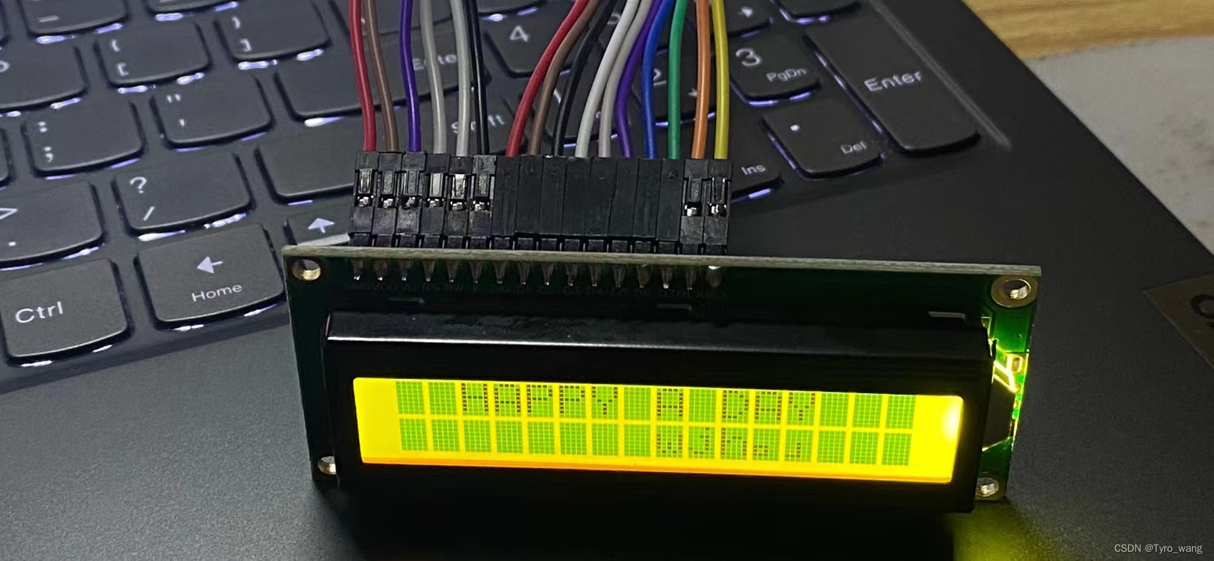
Finally, because I don’t have a potentiometer, I connected VL to GND for the highest contrast, but if the contrast is too high, ghosting will occur.
This can be adjusted using a potentiometer.