Introduction to communication protocols
Communication interface
- The purpose of communication: transfer data from one device to another device, expand the hardware system
- Communication protocol: Establish the rules for communication, and both parties in the communication send and receive data according to the protocol rules.

- Synchronous communications typically include clock signals.
- Simplex communication means that data can only go from one device to another device, but not the other way around. Half-duplex means that data can only go from one device to another device, and can come in the opposite direction, but not at the same time. Full-duplex means that data can only go from one device to another device, but not at the same time. Full-duplex means that data can only go from one device to another device, but not at the same time. , sending and receiving data can be done at the same time.
- Single-ended level communication usually needs to be connected to GND. Differential communication generally has strong anti-interference and data is not easily lost.
- Point-to-point devices can only send one device to one device, or one device can receive another device.
- Multi-device refers to one-to-many, many-to-one, and many-to-many connection methods.
- In I2C, the SCL pin refers to the clock signal and SDA refers to the data.
- In SPI, SCLK refers to the clock signal, MOSI refers to the host output data pin, MISO refers to the host input data pin, and CS is the chip select signal.
- CAN_H and CAN_L in CAN are used to differentially output data
- DP/D+ and DM/D- output signals in USB. The USB protocol also requires single-ended signals, so USB still needs to supply GND.

Serial communication
- The serial port is a widely used communication interface. The serial port is low in cost, easy to use, and has simple communication lines. It can realize mutual communication between multiple devices.
- The serial port of a single-chip microcomputer allows the single-chip computer to communicate with each other, the single-chip computer and a computer, and the single-chip computer and various modules. It greatly expands the application scope of the single-chip computer and enhances the hardware strength of the single-chip computer system.


Hardware circuit
- Simple two-way serial communication has two communication lines (sending end TX and receiving end RX)
- TX and RX need to be cross-connected
- When only one-way data transmission is required, only one communication line can be connected
- When the level standards are inconsistent, a level conversion chip needs to be added


Level standards
- The expression of data 1 and data 0 in level standard is the artificially specified correspondence between voltage and data in the transmission cable. There are three commonly used level standards for serial ports:
- TTL level: +3.3V or +5V means 1, 0V means 0
- RS232 level: -3V~-15V means 1, +3V to +15 means 0 (used in large machines, harsh environment, large level fluctuations)
- RS485 level: The voltage difference between the two lines + 2~ + 6V means 1, -2 to -6V means 0 (commonly used for differential signals)
Serial communication
Serial port parameters and timing
- Baud rate: the rate of serial communication
- Start bit: marks the beginning of a data frame, fixed to low level
- Data bit: payload of the data frame, 1 is high level, 0 is low level, low bit first
- Check digit: used for data verification, calculated based on the data bits
- Stop bit: used for data frame interval, fixed bit high level


USART Introduction
- USART (Universal Synchronous/Asynchronous Receiver/Transmitter) universal synchronous/asynchronous receiver and transmitter
- USART is an integrated hardware peripheral inside STM32. It can automatically generate data frame timing based on one byte of data in the data register and send it out from the TX pin. It can also automatically accept the data frame timing of the RX pin and splice it into one byte of data. , stored in the data register, directly read and write the register. Comes with built-in baud rate generator, up to 4.5Mbits/s
- Configurable data bit length (8, 9), stop bits (0.5, 1, 1.5, 2)
- Optional parity bit (no parity, odd parity, even parity)
- Supports synchronous mode, hardware flow control, DMA, smart card, IrDA, LIN
- STM32fF103 USART resources: USART1 (APB2 bus 72MHz), USART2 (APB1 bus 36MHz), USART3 (APB1 bus 36MHz)
USART block diagram

- TDR(Transmit DR) transmits the register, RDR(Recieve DR) receives the register, the two register addresses are the same
- The RXNE receiving register is not empty 1, indicating that data can be accepted, and the TXE transmitting register is empty 1, indicating that data can be sent.
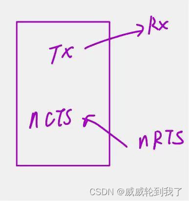
- Hardware flow control: The TX port is connected to the RX port, and nRTS is connected to the nCTS port, where nCTS represents Clear to send and nRTS represents Request to send.

USART basic structure

Data frame


Start bit detection

- Sampling at 16 times the baud rate, NE is the noise flag
Baud rate generator
- The baud rate of the transmitter and receiver is determined by the DIV in the baud rate register BRR

Code
- Turn on the clock and turn on the required USART and GPIO clocks
- GPIO initialization, configure TX as an output and RX as an input
- Configure USART and use a structure directly
- To configure the interruption of the acceptance function, just add the ITConfig and NVIC codes before turning on USART.
- Open switch control
#include "stm32f10x.h" // Device header
#include <stdio.h>
#include <stdarg.h>

uint8_t Serial_RxData;
uint8_t Serial_RxFlag;

/****
* @brief serial port initialization
* 1. Turn on the clock and turn on the required USART and GPIO clocks
* 2. GPIO initialization, configure TX as an output and RX as an input
* 3. Configure USART and use a structure directly
* 4. To configure the interruption of the acceptance function, just add the ITConfig and NVIC codes before turning on USART.
* 5. Turn on the switch control
*/
void serial_init(void)
{<!-- -->
RCC_APB2PeriphClockCmd(RCC_APB2Periph_USART1, ENABLE);
RCC_APB2PeriphClockCmd(RCC_APB2Periph_GPIOA, ENABLE);
\t
\t
GPIO_InitTypeDef GPIO_InitTypeDefstructure;
GPIO_InitTypeDefstructure.GPIO_Mode = GPIO_Mode_AF_PP;
GPIO_InitTypeDefstructure.GPIO_Pin = GPIO_Pin_9;
GPIO_InitTypeDefstructure.GPIO_Speed = GPIO_Speed_50MHz;
GPIO_Init(GPIOA, & amp;GPIO_InitTypeDefstructure);
\t
GPIO_InitTypeDefstructure.GPIO_Mode = GPIO_Mode_IN_FLOATING;
GPIO_InitTypeDefstructure.GPIO_Pin = GPIO_Pin_8;
GPIO_Init(GPIOA, & amp;GPIO_InitTypeDefstructure);
\t
\t
USART_InitTypeDef USART_InitTypeDefStructure;
USART_StructInit( & amp;USART_InitTypeDefStructure);
USART_InitTypeDefStructure.USART_BaudRate = 115200;
USART_InitTypeDefStructure.USART_HardwareFlowControl = USART_HardwareFlowControl_None;
USART_InitTypeDefStructure.USART_Mode = USART_Mode_Rx | USART_Mode_Tx;
USART_InitTypeDefStructure.USART_Parity = USART_Parity_No;
USART_InitTypeDefStructure.USART_StopBits = USART_StopBits_1;
USART_InitTypeDefStructure.USART_WordLength = USART_WordLength_8b;
\t
USART_Init(USART1, & amp;USART_InitTypeDefStructure);
\t
USART_ITConfig(USART1, USART_IT_RXNE, ENABLE);
\t
NVIC_PriorityGroupConfig(NVIC_PriorityGroup_2);
\t
NVIC_InitTypeDef NVIC_InitStructure;
NVIC_InitStructure.NVIC_IRQChannel = USART1_IRQn;
NVIC_InitStructure.NVIC_IRQChannelCmd = ENABLE;
NVIC_InitStructure.NVIC_IRQChannelPreemptionPriority = 1;
NVIC_InitStructure.NVIC_IRQChannelSubPriority = 1;
NVIC_Init( & amp;NVIC_InitStructure);
\t
USART_Cmd(USART1, ENABLE);
}

/**
  * @brief serial port output data
  */
void serial_sendData(uint8_t data)
{<!-- -->
USART_SendData(USART1, data);
while(USART_GetFlagStatus(USART1, USART_FLAG_TXE) == RESET);
\t
}

void serial_sendArray(uint8_t *pdata, uint16_t sz)
{<!-- -->
uint16_t i;
for(i = 0;i<sz;i + + ){<!-- -->
serial_sendData(pdata[i]);
}
}

void serial_sendString(char *pdata)
{<!-- -->
uint8_t i;
for(i = 0;pdata[i] != '\0';i + + )
{<!-- -->
serial_sendData(pdata[i]);
}
}

static uint32_t serial_pow(uint32_t base, uint8_t index)
{<!-- -->
uint8_t i;
uint32_t data = 1;
for(i=0;i<index;i + + )
{<!-- -->
data *= base;
}
return data;
}

void serial_sendNumber(uint32_t data, uint16_t length)
{<!-- -->
uint8_t i;
for(i=0;i<length;i + + )
{<!-- -->
serial_sendData(data / serial_pow(10, length - i - 1) % 10 + '0');
}
}
/**
* @brief printf搴枞眰闱爁putc鍙戦€?
*/
int fputc(int data, FILE *f)
{<!-- -->
serial_sendData(data);
return data;
}

/**
*@brief
*/
void serial_printf(char *format, ...)
{<!-- -->
char string[100];
va_list arg;
va_start(arg, format);
vsprintf(string, format, arg);
va_end(arg);
serial_sendString(string);
}

uint8_t Serial_GetRxFlag(void)
{<!-- -->
if (Serial_RxFlag == 1)
{<!-- -->
Serial_RxFlag = 0;
return 1;
}
return 0;
}

uint8_t Serial_GetRxData(void)
{<!-- -->
return Serial_RxData;
}

void USART1_IRQHandler(void)
{<!-- -->
if (USART_GetITStatus(USART1, USART_IT_RXNE) == SET)
{<!-- -->
Serial_RxData = USART_ReceiveData(USART1);
Serial_RxFlag = 1;
USART_ClearITPendingBit(USART1, USART_IT_RXNE);
}
}