1. Experimental purpose
*Master the method of controlling interrupts and timers in C51
*Master the principles and methods of using CH451 for keyboard input
*Master the interface and programming of DS18B20 temperature sensor
2. Experimental equipment
*MCU experiment box
*CH451 display module
*Temperature acquisition module (at the lower left of the SWITCH module area of the experimental box)
*Keil development system
3. Experimental Principle
CH451 keyboard input principle and working method

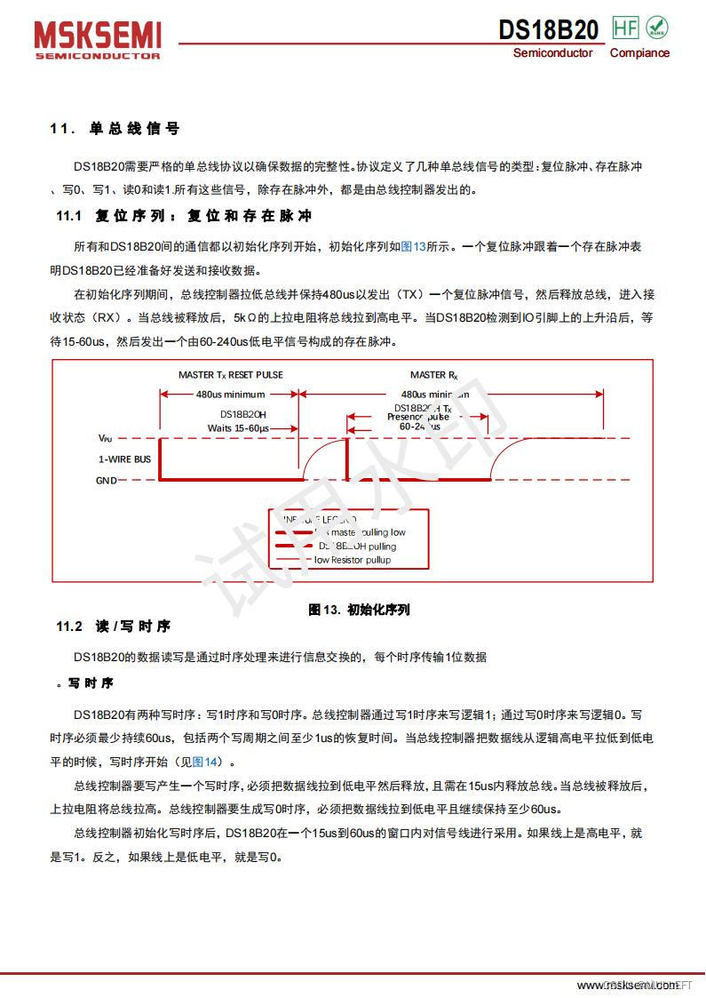
Principle of DS18B20 temperature sensor

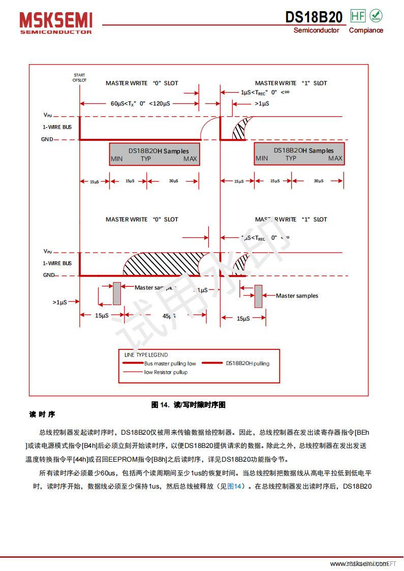
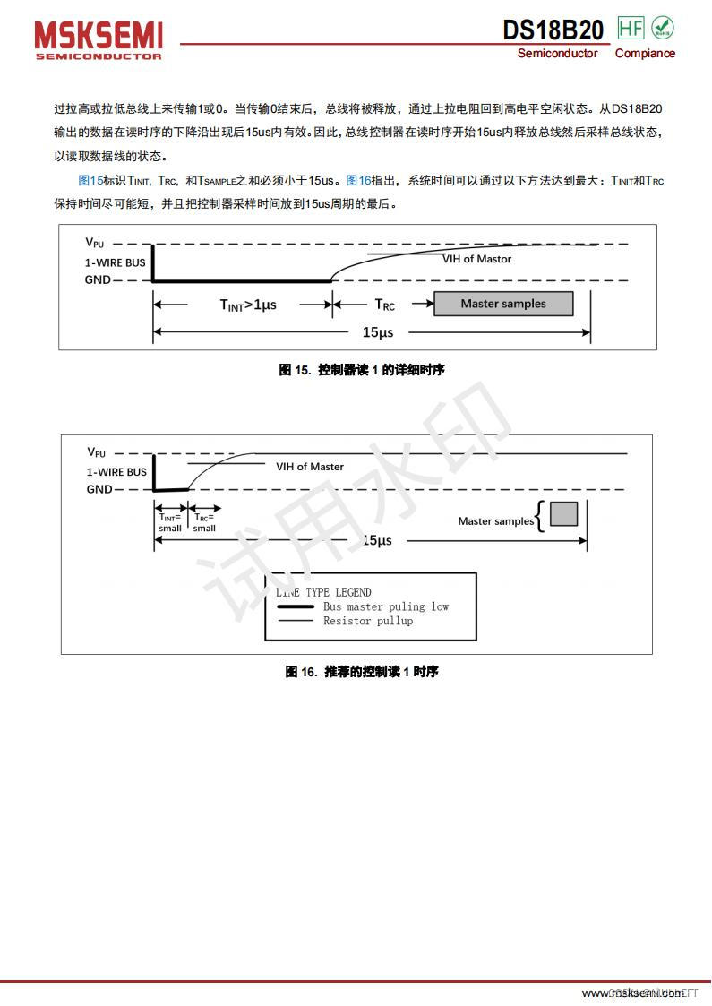
Principles and methods of single-line communication
4. Experimental content
Experimental content
Use C51 to write a program to implement a countdown table with temperature function
*The collected temperature is displayed on the right side of the digital tube, using decimal display, 1 digit after the decimal point, and refreshed regularly.
* Implement a countdown watch on the left side of the digital tube to display minutes (one digit is sufficient) and seconds for countdown.
*Use the keyboard to enter the initial value of the countdown table and control its operation
Experiment specific requirements
1. The keyboard control of the countdown watch includes the following functions:
* There are 10 numeric keys defined on the keyboard, and you can use the numeric keys to input a 3-digit initial value
* Customize several function keys to achieve: output initial value, start counting, pause, terminate counting and other functions
*The countdown watch must be able to be used continuously, not one-time use
* Robustness must be ensured, that is, the program must execute normally in response to incorrect key presses and other situations.
2. The temperature value should display a decimal point
5. Experimental steps
1. Design circuit connection scheme and connect equipment
2. It is recommended to follow the following steps for programming and debugging.
(1) Write a collection program to collect temperature and display it;
(2) Use the internal timer interrupt to write a countdown table program to display the countdown time;
(3) Write a keyboard input program to read the key codes and convert them;
(4) Write control logic to control the running status of the entire system so that all the above parts work together.
Reference circuit connection diagram
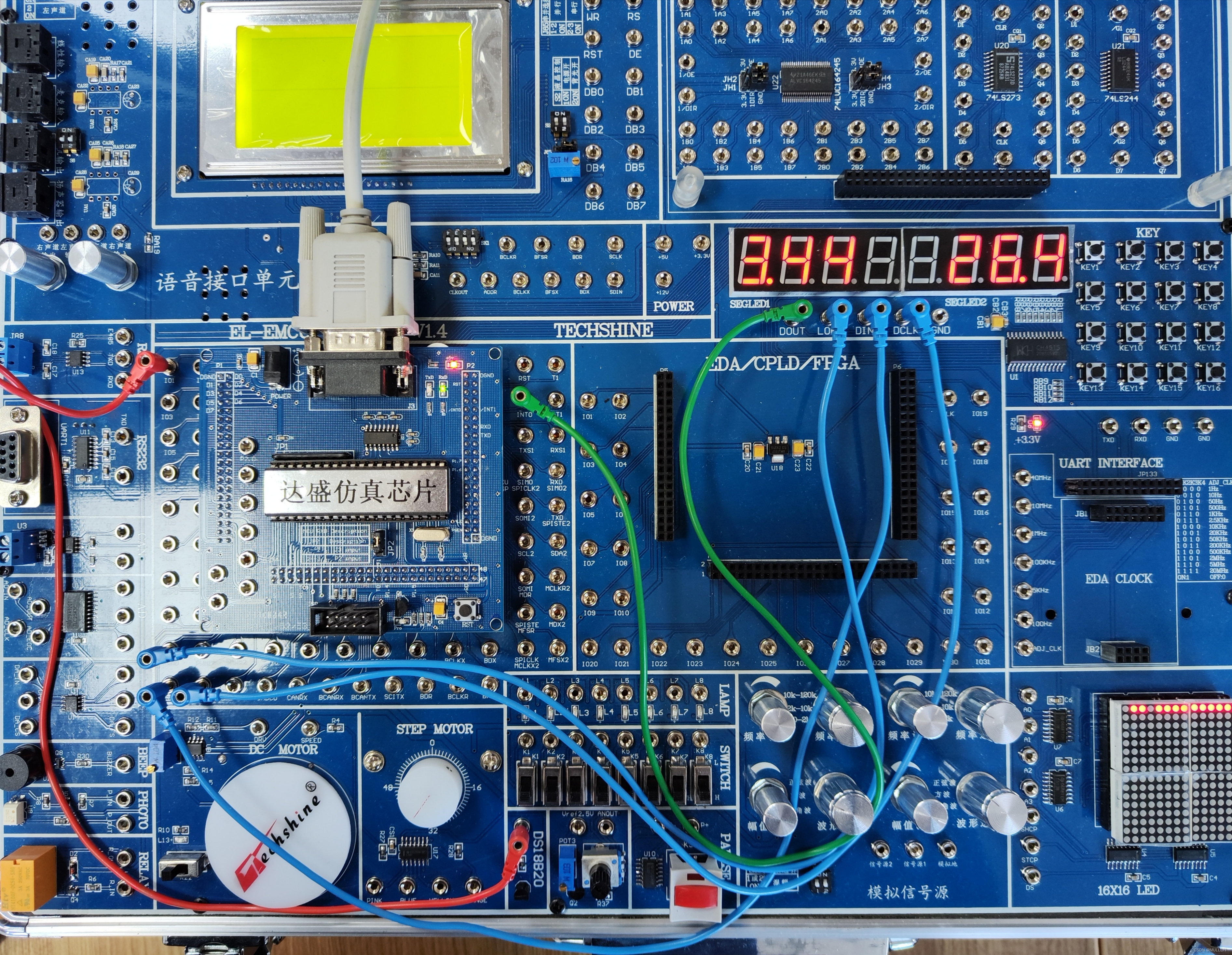
The DIN of the CH451 module is connected to SDA (corresponding to C51 chip pin P1.1), DCLK is connected to SCL (corresponding to C51 chip pin P1.2), LOAD is connected to PWM0 (corresponding to C51 chip pin P1.3), DOUT is connected to INT0, That is interrupt 0. The DQ end of DS18B20 is connected to P0.0, which is IO1.
reference code
//ch451.h
#ifndef __CH451_H__
#define __CH451_H__
#include<reg51.h>
#define CH451_RESET 0x0201 //Reset
#define CH451_LEFTMOV 0x0300 //Set the movement mode - move
#define CH451_LEFTCYC 0x0301 //Set the movement mode-left rotation
#define CH451_RIGHTMOV 0x0302 //Set the movement method-right shift
#define CH451_RIGHTCYC 0x0303 //Set movement mode-right rotation
#define CH451_SYSOFF 0x0400 //Turn off display, keyboard, and watchdog
#define CH451_SYSON1 0x0401 //Open display
#define CH451_SYSON2 0x0403 //Turn on display and keyboard
#define CH451_SYSON3 0x0407 //Enable display, keyboard, and watchdog functions
#define CH451_DSP 0x0500 //Set the default display mode
#define CH451_BCD 0x0580 //Set BCD decoding method
#define CH451_TWINKLE 0x0600 //Set flicker control
#define CH451_DIG0 0x0800 //Nigital tube bit 0 display
#define CH451_DIG1 0x0900 //Nigital tube bit 1 display
#define CH451_DIG2 0x0a00 //Nigital tube bit 2 display
#define CH451_DIG3 0x0b00 //Nigital tube bit 3 display
#define CH451_DIG4 0x0c00 //Nigital tube bit 4 display
#define CH451_DIG5 0x0d00 //Nigital tube bit 5 display
#define CH451_DIG6 0x0e00 //Nigital tube bit 6 display
#define CH451_DIG7 0x0f00 //Nigital tube bit 7 display

#define USE_KEY 1//If you use keyboard interrupt, please define
sbit ch451_load = P1^3; //Serial command loading, rising delay activated
sbit ch451_din = P1^1; // Serial data output, connected to the data input of CH451
sbit ch451_dclk = P1^2; //Serial data clock rising delay is activated
sbit ch451_dout = P3^2; //INT0 corresponds to P3.2, keyboard interrupt and key value data input, connected to the data output of CH451
extern unsigned char ch451_key;// Global variable, stores the key value read in the keyboard interrupt
void ch451_init();
void ch451_write(unsigned int command);
unsigned char ch451_read();
void ch451_inter();

#endif
//ch451.c
#include "ch451.h"

//Initialize subroutine

void ch451_init()
{
  ch451_din=0; //First low and then high, select 4-wire input
  ch451_din=1;
#ifdef USE_KEY
  IT1=0; //Set falling edge trigger
  IE1=0; //clear interrupt flag
  PX1=0; //Set low priority
  EX1=1; //Enable interrupt
#endif

}
//************************************************ *****
//Output command subroutine
//Define an unsigned integer variable to store the 12-byte command word.
 void ch451_write(unsigned int command)
{
  unsigned char i;
#ifdef USE_KEY
  EX1=0; //Disable keyboard interrupts
#endif
  ch451_load=0; //Command starts
  for(i=0;i<12;i + + ){ //Send 12-bit data, low bit first
    ch451_din=command &1;
    ch451_dclk=0;
    command>>=1;
    ch451_dclk=1; //valid on rising edge
  }
  ch451_load=1; //Load data
#ifdef USE_KEY
  EX1=1;
#endif
}

#ifdef USE_KEY

//************************************************ *
//Enter the command subroutine, and the MCU reads one byte from 451
 unsigned char ch451_read()
{
  unsigned char i;
  unsigned char command,keycode; //Define the command word and data memory
  EX1=0; //Middle section
  command=0x07; //Input read 451 command word
  ch451_load=0;
  for(i=0;i<4;i + + ){

    ch451_din=command & amp;1; //Send in the lowest bit
    ch451_dclk=0;
    command>>=1; //Move one position to the right
    ch451_dclk=1; //Generate clock rising edge lock to notify CH451 to input bit data
 }
  ch451_load=1; // Generate a loading rising edge to notify CH451 to process the command data
  keycode=0; //Clear keycode
  for(i=0;i<7;i + + ){
    keycode<<=1; //Move data into keycode, high bit first, low bit last
    keycode|=ch451_dout; //Read the data of 451 from high to low
    ch451_dclk=0; //Generate the rising edge of the clock to notify CH451 to output the next bit
    ch451_dclk=1;
 }
  IE1=0; //clear interrupt flag
  EX1=1;
  return(keycode); //Return the key value
}
//************************************************ *
//Interrupt subroutine uses interrupt 0

void ch451_inter() interrupt 0//External interrupt 0 (INT0) corresponds to interrupt 0, external interrupt 1 (INT1) corresponds to interrupt 2
{
  unsigned char i; //Define loop variables
  unsigned char command,keycode; //Define control word register and intermediate variable timer
  command=0x07; //Read the high 4 bits of the key value command 0111B
  ch451_load=0; //Command starts
  for(i=0;i<4;i + + ){
    ch451_din=command & amp;1; //low bit first, high bit last
    ch451_dclk=0;
    command>>=1; //Shift right one bit
    ch451_dclk=1; //Generate clock rising edge lock to notify CH451 to input bit data
 }
  ch451_load=1; // Generate a loading rising edge to notify CH451 to process the command data
  keycode=0; //Clear keycode
  for(i=0;i<7;i + + ){
    keycode<<=1; //The data is shifted by one bit, with the high bit in front and the low bit in the back
    keycode|=ch451_dout; //Read the data of 451 from high to low
    ch451_dclk=0; //Generate the rising edge of the clock to notify CH451 to output the next bit
    ch451_dclk=1;
 }
  ch451_key=keycode; //Save the last key value. The relationship between the read key code and the key value needs to be tested.
  IE0=0; //clear interrupt flag
}

//**********************************************

#endif
//ds18b20.h
#ifndef __DS18B20_H__
#define __DS18B20_H__
#include<reg51.h>
//Define bit variable DQ as a single bus for communication with 18B20
// Currently using P0.0, you can modify it as needed
sbit DQ = P0^0;
#define DQ_H DQ = 1;
#define DQ_L DQ = 0;

//Function prototype declaration
void reset_ds18b20(void);
void write_byte(unsigned char dat);
unsigned char read_byte(void);

#endif
//ds18b20.c
#include "ds18b20.h"
#include <intrins.h>


/*
Execution time: approximately equal to 10*n microseconds, when the main frequency is 12MHz, add a nop
If you consider the execution of other statements, you can subtract another nop
*/
void delay_10us(unsigned char n){
unsigned char i;
for(i=n; i>0; --i){
_nop_();
//_nop_(); //The main frequency is 12MHz
}
}


/****************************************************** *************************************************** *******
Function name: DS18B20 initialization subroutine
Input parameters: None
Output parameters: none
Function returns: None
*************************************************** *************************************************** ******/

void reset_ds18b20(void){
  DQ_H; // DQ is set high first
delay_10us(10); // Delay
  DQ_L; //Send reset pulse
delay_10us(60); // Delay (480us - 960us)
  DQ_H; //Pull the data line high
delay_10us(24); // DS18B20 will generate a response pulse, lasting 60-240us
}


/****************************************************** *************************************************** *******
Function name: Write one byte of data to DS18B20
Input parameters: data
Output parameters: none
Function returns: None
*************************************************** *************************************************** ******/
void write_byte(unsigned char dat){
unsigned char i=0;
for (i = 8; i > 0; i--){
//To avoid adding the judgment time to the timing, put the judgment outside
if(dat & 0x01)
        {
DQ_L;
_nop_(); _nop_(); //Delay 2us
            DQ_H; //Release the bus
delay_10us(6);
        }
        else
        {
DQ_L;
delay_10us(6);
            DQ_H;
_nop_(); _nop_(); //Delay 2us
        }
dat>>=1;
}
delay_10us(3);
}
/****************************************************** *************************************************** *******
Function name: function to read one byte of data from ds18b20
Input parameters: none
Output parameters: none
Function returns: bytes read
*************************************************** *************************************************** ******/

unsigned char read_byte(void)
{
unsigned char i = 0;
unsigned char dat = 0;
bit b;
    //Read the low bit first and then the high bit
    for (i = 8; i > 0; i--)
{
DQ_L;
_nop_(); _nop_(); //Delay 2us
DQ_H; //Release the bus
dat >>= 1; //Data must be read within 15us, use the time occupancy of this expression
b=DQ;

    if (DQ){
            dat|=0x80;
        }

delay_10us(6);
}
    return(dat);
}
//main.c
#include<reg51.h>
#include <intrins.h>
#include "ch451.h"
#include "ds18b20.h"

//Global variables needed for countdown table
unsigned int cnt=0; //Record the number of interruptions
unsigned char second_i=0; //Initialize second digit digital tube
unsigned char second_t=0; //Initialize tens of seconds digital tube
unsigned char min=0; //Initialize the minutes digital tube
unsigned char first_start=1;//The countdown table starts counting for the first time
enum COUNT_DOWN_TIMER_STATE{INITIAL,INPUT1,INPUT2,INPUT3,RUN,PAUSE};
enum COUNT_DOWN_TIMER_STATE timer_state=INITIAL;

/****************************************************** **********
Countdown timer state machine: Pass in the key value to the countdown timer, and the countdown timer responds according to the current state and the incoming key value
*************************************************** *******/
void count_down_timer(unsigned char key_value){
    switch(timer_state){
            case INITIAL:
                 if(key_value==12)timer_state=INPUT1;//Input initial value
            break;
            case INPUT1:
                if(key_value>=0 & amp; & amp;key_value<=9){
                    min=key_value;
                    ch451_write(CH451_DIG7|min|0x80);
                    timer_state=INPUT2;
                }
            break;
            case INPUT2:
                if(key_value>=0 & amp; & amp;key_value<=9){
                    second_t=key_value;
                    ch451_write(CH451_DIG6|second_t);
timer_state=INPUT3;
                }
            break;
            case INPUT3:
                if(key_value>=0 & amp; & amp;key_value<=9){
                    second_i=key_value;
                    ch451_write(CH451_DIG5|second_i);
first_start=1;
                    timer_state=PAUSE;
                }
            break;
            case PAUSE:
                if(key_value==13){//Start timing
                    TMOD=0x01; //T0 mode is 1
                    if(first_start){//If it is the first time to start the countdown, rather than continuing the countdown after a pause
                        TH0=0xfc;//The main frequency of the CPU used in the experimental box is 11.0892MHz, and the frequency of the counter plus one is 11.0892/12=0.9241MHz
                        TL0=0x64;//Timing 1ms requires 10^(-3)*0.9241M=924.1,65536-924=64612=0FC64H
                        first_start=0;
                    }
ET0=1;//ES is the serial port interrupt enable bit;
                            //ET1 and ET0 are the interrupt enable bits of T1 and T0;
                            //EX1 and EX0 are the interrupt enable bits of external interrupts INT1 and INT0.
                            //When these bits are 1, the corresponding interrupt request is allowed to be responded to, and when they are 0, they are masked.
TR0=1;//Start T0
                   PT0=0; //T0 interrupt is low priority

                   timer_state=RUN;
                }
                break;
            case RUN:
                if(key_value==14){
                    TR0=0;//Close T0
                    timer_state=PAUSE;
                }
            break;
    }
    if(key_value==15){//terminate timing
        ET0=0;//Turn off interrupt
       timer_state=INITIAL;//return to initial state
    }
}

/****************************************************** **********
Timer T0 interrupt
*************************************************** *******/
void InterruptTimer0() interrupt 1
{
TH0=0xfc; //Reassign value
TL0=0x64;
cnt + + ;//Generate an interrupt every 1ms, each interrupt causes cnt + +, 1000 interrupts is 1s
    //Every thousand timer interrupts, modify the minutes and seconds
if(cnt>=1000) //Interruption accumulates 1000 1s
{
cnt=0; //clear to 0
second_i--;
if(second_i==0xFF){ //Minus one overflow
second_i=9;
second_t--;
if(second_t==0xFF){
second_t=5;
min--;
if(min==0xFF){
min=9;
                     second_t=5;
                     second_i=9;
}
}
}
}
}


/****************************************************** **********
read temperature
*************************************************** *******/
unsigned int read_temperature()
{
  unsigned int a=0,b=0,t=0;
  float tt=0;
  reset_ds18b20();
  write_byte(0xCC); //Skip the operation of reading the sequence number and column number 1100 1100
  write_byte(0x44); //Start temperature conversion 0100 0100
  reset_ds18b20();
  write_byte(0xCC); //Skip the operation of reading the serial number and column number
  write_byte(0xBE); //Read temperature register 1011 1110
  a=read_byte(); //Read the lower 8 bits
  b=read_byte(); //Read the upper 8 bits
  t=b;
  t<<=8;
  t=t|a;
  if(t & amp;0xf800)//The high five bits are the sign bits, 1 indicates negative temperature
  {
t=~t + 1;
//temperature_sign=1;//Temperature positive and negative
  }
  //else temperature_sign=0;
  tt=t*0.0625;//The default accuracy of the chip when powered on is 12 bits, and the temperature resolution is 0.0625℃
  t=(unsigned int)(tt*10 + 0.5); //Enlarge the output 10 times and round off
  return(t);
}

/****************************************************** **********
Display temperature
*************************************************** *******/
void display_temperature()
{
    unsigned char temperature_h; //hundred digit after temperature * 10
    unsigned char temperature_t;//tens digit
    unsigned char temperature_i;//units digit
    unsigned int f;
    f=read_temperature()-10; //Get the temperature value and subtract the temperature drift error of DS18B20
    temperature_i=f;
    f=f/10;
    temperature_t=f;
    f=f/10;
    temperature_h=f;
    ch451_write(CH451_DIG0|temperature_i);
    ch451_write(CH451_DIG1|temperature_t|0x80);//0x80 means adding a decimal point
    ch451_write(CH451_DIG2|temperature_h);
}


/****************************************************** *
Conversion subroutine: convert the key code obtained by interrupt into key value
*************************************************** /
unsigned char tran(unsigned char key){
    key &=0x3f; //Only keep the lower six bits
    if (key<4)return key;
    else if(key<12)return key-4;
    else if(key<20)return key-8;
    else if(key<28)return key-12;
}

int main(){
    unsigned char key_value;
unsigned int i;
    ch451_init(); //Initialization
    ch451_write(0x403);//Set system parameters: 0100000[CKHF][DPLR][WDOG][KEYB][DISP]B, common anode, low level active, DPLR=0
    ch451_write(0x580);//580H=010110000000B, the eighth digit from the right indicates the BCD decoding method
    ch451_write(CH451_DIG3|0x10);//space
    ch451_write(CH451_DIG4|0x10);//space
    //ch451_write(0x500);//500H=010100000000B, no decoding mode


    while(1){
        //The operation of DS18B20 has strict timing requirements, and many processes cannot be interrupted, so turn off interrupts first.
        EA=0; //Turn off interrupt
        display_temperature();
EA=1; //Enable interrupt

if(timer_state==RUN){
ch451_write(CH451_DIG7|min|0x80);//The seventh digit of ch451 displays the minutes with a decimal point
            ch451_write(CH451_DIG6|second_t);//The sixth digit of ch451 displays tens of seconds
            ch451_write(CH451_DIG5|second_i);//The fifth digit of ch451 displays the second digit
}

        EX0=1;//INT0 interrupt enabled
        PX0=1;//INT0 interrupt is high priority
        ch451_key=0x0ff;
for(i=10000; i>0; --i){
if(ch451_key!=0xff){
            key_value=ch451_key;
            key_value=tran(key_value);
            ch451_key=0x0ff;
            count_down_timer(key_value);
            break;
          }
}
        EX0=0;
    }
}
*Code Description:

Programming flow chart

Countdown timer state machine
*Reference materials
ch451 technical manual: CH451DS1.PDF – Nanjing Qinheng Microelectronics Co., Ltd.
ch451 development resources: CH451IF.ZIP – Nanjing Qinheng Microelectronics Co., Ltd.