7.1ADC test
ADC (Analog to Digital Converter) converts analog quantities into digital quantities. Some peripherals output analog voltages. In this case, you need to use ADC to convert analog quantities into digital quantities for calculation. It is often used for detection in low-power devices. Battery voltage, HC32L196 internally integrates a 12-bit ADC with 30 input channels, including 26 external pin inputs, 1 internal temperature sensor voltage, 1 1/3 power supply voltage, 1 built-in BGR1.2V voltage, DAC internal output

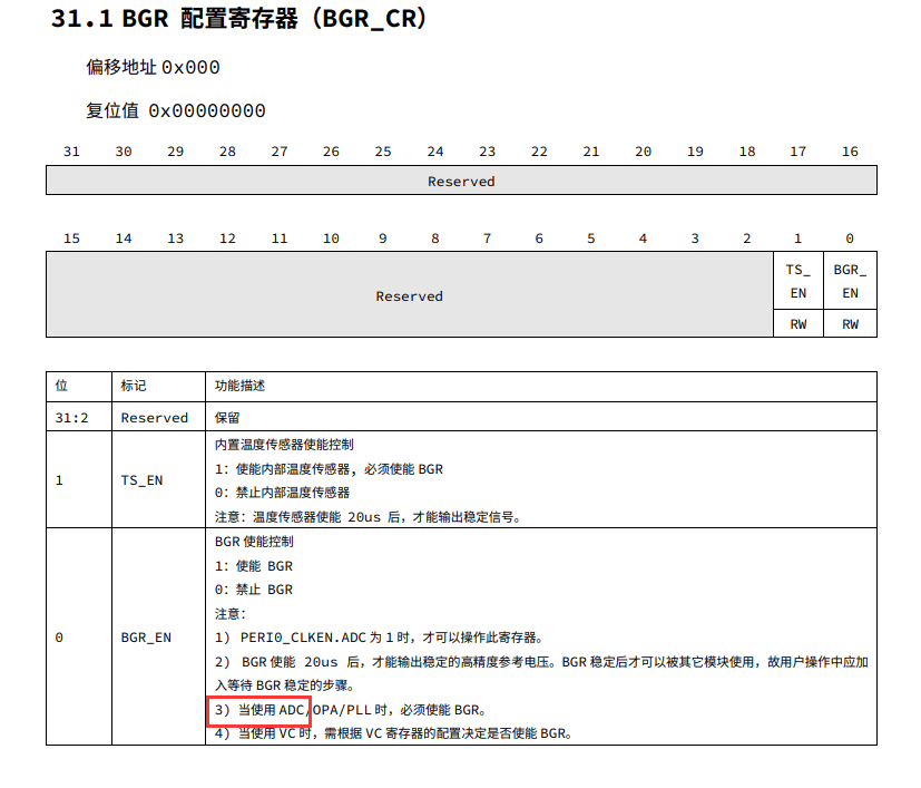
When using the ADC, you also need to enable the BGR control register
Let’s test the built-in temperature sensor first. It is more convenient to measure without needing to connect other external equipment.
Initialize ADC module
copy
void adc_init()

{

    stc_adc_cfg_t stcAdcCfg;

    DDL_ZERO_STRUCT(stcAdcCfg);

    ///< Turn on ADC/BGR peripheral clock

    Sysctrl_SetPeripheralGate(SysctrlPeripheralAdcBgr, TRUE);

    Bgr_BgrEnable();

    Bgr_TempSensorEnable();

    ///< ADC initialization configuration

    stcAdcCfg.enAdcMode = AdcSglMode; ///<sampling mode-single

    stcAdcCfg.enAdcClkDiv = AdcMskClkDiv1; ///<sampling frequency division-1

    stcAdcCfg.enAdcSampCycleSel = AdcMskSampCycle12Clk; ///<number of sampling cycles-12

    stcAdcCfg.enAdcRefVolSel = AdcMskRefVolSelInBgr2p5; ///<Reference voltage selection-internal 2.5V

    stcAdcCfg.enAdcOpBuf = AdcMskBufEnable; ///<Open amplifier

    stcAdcCfg.enInRef = AdcMskInRefEnable; ///<Internal reference voltage enable-on

    stcAdcCfg.enAdcAlign = AdcAlignRight; ///<Conversion result alignment-right

    Adc_Init( & amp;stcAdcCfg);

    ///< Configure single sampling channel

    Adc_CfgSglChannel(AdcAiTsInput);

    ///< Start single continuous sampling

    Adc_SGL_Always_Start();

}
Then I found an error in the driver file:
After finishing writing, I found that errors were reported here all the time, and bgr.h was already included.
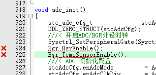
After checking bgr.h, I found that it was actually CRC, and my project happened to include crc.h. After modifying it to BGR, the problem was solved. When I opened the original file in the HC32L19x_DDL_Rev1.2.0.zip compressed package, it was also CRC, as was the 1.1 one. I hope it will be official. Will fix it later

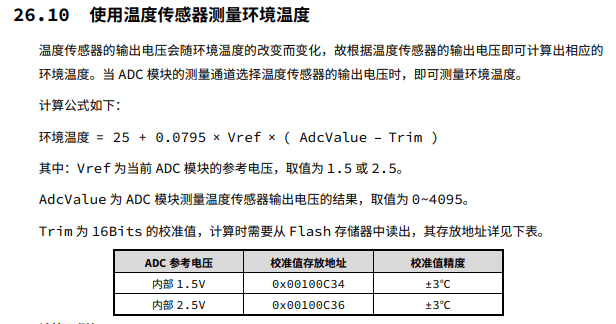
There is a method for calculating temperature in the manual.
Print adc and temperature in the main loop
copy
int32_t main(void)

{

    floatTemF;

    uint16_t adc_trim;

    uint32_t adc_result;

    xth_init();

    //Clock frequency division setting

    Sysctrl_SetHCLKDiv(SysctrlHclkDiv1);

    Sysctrl_SetPCLKDiv(SysctrlPclkDiv1);

    flash_init();

    led_init();

    key_init();

    timer0_init();

    uart0_io_init();

    uart0_init();

    adc_init();

    adc_trim = *((unsigned short int *)0x00100C36);

    while(1)

    {

        if(TRUE == Adc_GetIrqStatus(AdcMskIrqSgl))

        {

            ///< Get sample value

            adc_result = Adc_GetSglResult();

            TemF = 25 + 0.0795 * 2.5 * ( adc_result - adc_trim );

            printf("ADC X% calibration value: X temperature: %0.1f℃",adc_result,adc_trim,TemF);

            Adc_ClrIrqStatus(AdcMskIrqSgl);

        }

        yuyy_delay_ms(1000);

    }

}
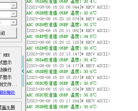
running result
Next, test the external input. Use the joystick of this game controller as input, and select PA00 and PA01 as input in the XY direction.

Select AVDD for reference voltage, sample channels 0 and 1, initialize IO and ADC modules
copy
void adc_io_init()

{

    Sysctrl_SetPeripheralGate(SysctrlPeripheralGpio, TRUE);

    Gpio_SetAnalogMode(GpioPortA, GpioPin0); //PA00 (AIN0)

    Gpio_SetAnalogMode(GpioPortA, GpioPin1); //PA01 (AIN1)

}

void adc_init()

{

    stc_adc_cfg_t stcAdcCfg;

    stc_adc_sqr_cfg_t stcAdcSqrCfg;

    DDL_ZERO_STRUCT(stcAdcCfg);

    ///< Turn on ADC/BGR peripheral clock

    Sysctrl_SetPeripheralGate(SysctrlPeripheralAdcBgr, TRUE);

    Bgr_BgrEnable();

    ///< ADC initialization configuration

    stcAdcCfg.enAdcMode = AdcScanMode; ///<Sampling Mode-Scan

    stcAdcCfg.enAdcClkDiv = AdcMskClkDiv1; ///<sampling frequency division-1

    stcAdcCfg.enAdcSampCycleSel = AdcMskSampCycle8Clk; ///<number of sampling cycles-8

    stcAdcCfg.enAdcRefVolSel = AdcMskRefVolSelAVDD; ///<Reference voltage selection-AVDD

    stcAdcCfg.enAdcOpBuf = AdcMskBufDisable; ///<Open amplifier

    stcAdcCfg.enInRef = AdcMskInRefDisable; ///<Internal reference voltage enable-off

    stcAdcCfg.enAdcAlign = AdcAlignRight; ///<Conversion result alignment-right

    Adc_Init( & amp;stcAdcCfg);


    ///< Sequential scan mode function and channel configuration

    ///< Note: In scan mode, when the number of configuration conversions is n, the configuration range of the conversion channel must be [SQRCH(0)MUX,SQRCH(n-1)MUX]

    stcAdcSqrCfg.bSqrDmaTrig = FALSE;

    stcAdcSqrCfg.enResultAcc = AdcResultAccDisable;

    stcAdcSqrCfg.u8SqrCnt = 2;

    Adc_SqrModeCfg( & amp;stcAdcSqrCfg);


    Adc_CfgSqrChannel(AdcSQRCH0MUX, AdcExInputCH0);

    Adc_CfgSqrChannel(AdcSQRCH1MUX, AdcExInputCH1);


    ///< Start sequential scan sampling

    Adc_SQR_Start();

}
Print ADC value in main loop
copy
int32_t main(void)
{
uint32_t adcresult0;
uint32_t adcresult1;
xth_init();
//Clock frequency division setting
Sysctrl_SetHCLKDiv(SysctrlHclkDiv1);
Sysctrl_SetPCLKDiv(SysctrlPclkDiv1);
flash_init();
led_init();
key_init();
uart0_io_init();
uart0_init();
adc_io_init();
adc_init();
while(1)
{
if(TRUE == Adc_GetIrqStatus(AdcMskIrqSqr))
{
Adc_ClrIrqStatus(AdcMskIrqSqr);
adcresult0 = Adc_GetSqrResult(AdcSQRCH0MUX); //Get sequential scanning channel 0
adcresult1 = Adc_GetSqrResult(AdcSQRCH1MUX); //Get sequential scanning channel 1
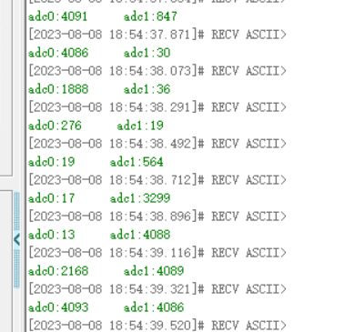
printf("adc0:%d adc1:%d",adcresult0,adcresult1);
Adc_SQR_Start();
}
yuyy_delay_ms(200);
}
}
Shake the joystick to view changes in the printed ADC value on the serial port tool.
7.2DAC
DAC (Digital to Analog Converter) is the opposite of ADC analog-to-digital conversion. It converts digital quantity into analog quantity output. HC32L196 integrates a 12-bit single-channel DAC inside, and the output IO is PA04

Use the DAC to output some waveforms, press the button to switch waveforms, and initialize the IO and DAC modules
copy
void dac_io_init()

{

    Sysctrl_SetPeripheralGate(SysctrlPeripheralGpio, TRUE); // Enable the peripheral clock of the GPIO module

    Gpio_SetAnalogMode(GpioPortA, GpioPin4); //PA04 is used as the analog output of the DAC

}


void dac_init()

{

    stc_dac_cfg_t dac_initstruct;

    Sysctrl_SetPeripheralGate(SysctrlPeripheralDac, TRUE); ///< Enable the clock of the DAC module

    dac_initstruct.boff_t = DacBoffDisable;

    dac_initstruct.ten_t = DacTenDisable;

    dac_initstruct.sref_t = DacVoltageAvcc;

    dac_initstruct.wave_t = DacWaveDisable;

    dac_initstruct.mamp_t = DacMenp4095;

    dac_initstruct.tsel_t = DacSwTriger; ///< Software triggering method

    dac_initstruct.align = DacRightAlign; ///< Right alignment

    dac_initstruct.dhr12 = 0;

    Dac_Init( & amp;dac_initstruct);

    Dac_Cmd(TRUE);

}
Generate waveform
copy
void proc_dac_wave()

{

    uint8_t changed = 0;

    switch(wavetype)

    {

        case 0:

            if(wavestep > 0)

                wavestep -= 1;

            else

            {

                if(dacvalue == 0)

                    dacvalue = 255;

                else

                    dacvalue = 0;

                changed = 1;

                wavestep = 9;

            }

            break;

        case 1:

            dacvalue + =1;

            changed = 1;

            break;

        case 2:

            if(wavestep > 0)

                wavestep -= 1;

            else

            {

                wavestep = 10;

                dacvalue + =15;

                changed = 1;

            }

            break;

        case 3:

            if(wavestep < 255)

            {

                dacvalue=wavestep;

                changed = 1;

            }

            else if(wavestep > 300 & amp; & amp; wavestep < 556)

            {

                dacvalue= 555 - wavestep;

                changed = 1;

            }

            if(wavestep < 600)

                wavestep + + ;

            else

                wavestep = 0;

            break;

        case 4:

            if(wavestep < 90)

            {

                dacvalue = sinvalues[wavestep];

                changed = 1;

            }

            else

            {

                dacvalue = sinvalues[180 - wavestep];

                changed = 1;

            }

            if(wavestep < 179)

                wavestep + + ;

            else

                wavestep = 0;

            break;

        case 5:

            if(wavestep < 90)

            {

                dacvalue = 127 + (sinvalues[wavestep]/2);

                changed = 1;

            }

            else

            {

                dacvalue = 128 - (sinvalues[180 - wavestep]/2);

                changed = 1;

            }

            if(wavestep < 179)

                wavestep + + ;

            else

                wavestep = 0;

            break;

        case 6:

            if(wavestep < 90)

            {

                dacvalue = 127 + (sinvalues[wavestep]/2);

                changed = 1;

            }

            else if(wavestep < 180)

            {

                dacvalue = 127 + (sinvalues[180 - wavestep]/2);

                changed = 1;

            }

            else if(wavestep < 270)

            {

                dacvalue = 128 - (sinvalues[wavestep - 180]/2);

                changed = 1;

            }

            else

            {

                dacvalue = 128 - (sinvalues[360 - wavestep]/2);

                changed = 1;

            }

            if(wavestep < 359)

                wavestep + + ;

            else

                wavestep = 0;

            break;

        default:

            break;

    }

    if(changed > 0)

        Dac_SetChannelData(DacRightAlign,DacBit8,dacvalue);

}
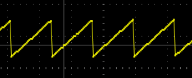
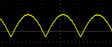
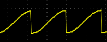
Waveform effect display, not that the oscilloscope waveform is a bit distorted


————————–
Author: yuyy1989
Link: https://bbs.21ic.com/icview-3319844-1-1.html
Source: 21ic.com
This article has received the originality/original award label, and the copyright belongs to 21ic. It is prohibited to be reproduced by anyone without permission.