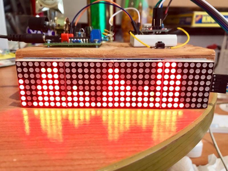
This project uses Arduino and four dot matrix screens to realize the visual display of 32-frequency audio (music) spectrum.
A lot of space is spent here to explain its principles (it may be slightly difficult for beginners to understand), and a complete schematic diagram and source code are provided. If you like to watch music dance to the sound intuitively, you can give it a try!
Materials list
Arduino Nano R3 × 1
Resistor 10k ohms × 1
Resistor 4.75k ohm × 3
Capacitor 100nF × 2
Resistor 100K ohm × 2
Tact switch 12mm × 1
LED display 32X8 × 1
5V power supply (for USB power supply) × 1
Main features
1. Use the easy-to-install libraries arduinoFFT and MD_MAX72xx.
2. Supports five different display modes, which can be switched through buttons.
3. The left and right channels of the audio signal are mixed without missing any beat.
4. The prototype uses 32×8 LED dot matrix, you can change it at will.
5. Audio can be input from headphones or the Line-Out input of the playback device.
Project flow chart

Schematic diagram

System principle description
The Arduino board (ATmega328P) has a built-in analog-to-digital converter (ADC) that converts the input audio signal into digital samples. The ADC was set up to sample the input signal with a clock frequency of 38.46khz. This is accomplished by configuring the ADC prescaler to divide by 32. The sampling frequency is 38.64Khz which means digital samples can be taken up to an input frequency of 19.32Kz (Nyquist theorem), which is very good for audio signals.
To display the spectrum of the audio signal, the left and right channels are mixed together and fed back to the A0 analog input of the ADC. You can use more than one minute of audio cable to feed the signal to both the spectrum analyzer and another amplifier (if necessary).
The ADC is set up to use an external reference voltage. In this project, the reference voltage comes from the 3.3v regulated power supply on the Arduino board. When the analog signal oscillates around zero voltage, we need to configure a DC bias on the analog input of the ADC. This ensures that the ADC output does not clip negative periods of the input signal. The same 3.3v regulated voltage is divided by two resistors R1 and R2 and then fed back to the analog input for DC biasing. With this DC bias, the ADC will produce 512 in the output even if the input signal is disconnected. Later in the code this 512 will be erased by the DC offset so that the reading represents the actual change in the input signal.
The ArduinoFFT library is the core code for converting an input analog signal into a frequency spectrum. This library is easy to use and the output is very accurate. The prototype was configured to generate 64 samples and use these samples to perform the FFT. The ArduinoFFT library can perform FFT on samples between 16 and 128, which can be configured in the program. But the arduinoFFT library is slow to calculate with 128 samples, so I stuck with the highest value of 64, which works best.
The display used in this project is a 32 column × 8 row LED matrix. The MD_MAX72xx library makes display control widgets very easy. This library provides functionality to turn on/off any number of LEDs being used in the program. The amplitude of each band is mapped between 0 and 8, depending on how many LEDs in each column are turned on.
The program offers five display modes, and you can easily modify or create different modes. This project uses buttons to switch modes.
Frequency response

Experiments have proven that the system can respond to frequencies up to 18.6Khz.
For more information about this project, please visit my GitHub: https://github.com/shajeebtm/Arduino-audio-spectrum-visualizer-analyzer/
Connect input
You can input audio into a spectrum analyzer in a variety of ways. You can do this from the Line-Out input of your music player/amplifier. Other options are to get the audio from the headphone output of your phone/music system. I don’t recommend using another microphone to receive audio, as the signal level and frequency response will include many factors.
Below is an example diagram of connecting a music player/amplifier to a spectrum display.

Below is an example diagram of connecting the headphone output of a mobile phone to a spectrum display.

No sound comes from your phone/music system when you connect the cable to the headphone output. If you want to hear the audio and display it, you have to separate the audio and use another amplifier.
Code
#include <arduinoFFT.h>
#include <MD_MAX72xx.h>
#include <SPI.h>

#define SAMPLES 64 //Must be a power of 2
#define HARDWARE_TYPE MD_MAX72XX::FC16_HW // Set display type so that MD_MAX72xx library treets it properly
#define MAX_DEVICES 4 // Total number display modules
#define CLK_PIN 13 // Clock pin to communicate with display
#define DATA_PIN 11 // Data pin to communicate with display
#define CS_PIN 10 // Control pin to communicate with display
#define xres 32 // Total number of columns in the display, must be <= SAMPLES/2
#define yres 8 // Total number of rows in the display


int MY_ARRAY[]={0, 128, 192, 224, 240, 248, 252, 254, 255}; // default = standard pattern
int MY_MODE_1[]={0, 128, 192, 224, 240, 248, 252, 254, 255}; // standard pattern
int MY_MODE_2[]={0, 128, 64, 32, 16, 8, 4, 2, 1}; // only peak pattern
int MY_MODE_3[]={0, 128, 192, 160, 144, 136, 132, 130, 129}; // only peak + bottom point
int MY_MODE_4[]={0, 128, 192, 160, 208, 232, 244, 250, 253}; // one gap in the top, 3rd light onwards
int MY_MODE_5[]={0, 1, 3, 7, 15, 31, 63, 127, 255}; // standard pattern, mirrored vertically


double vReal[SAMPLES];
double vImag[SAMPLES];
char data_avgs[xres];

int yvalue;
int displaycolumn, displayvalue;
int peaks[xres];
const int buttonPin = 5; // the number of the pushbutton pin
int state = HIGH; // the current reading from the input pin
int previousState = LOW; // the previous reading from the input pin
int displaymode = 1;
unsigned long lastDebounceTime = 0; // the last time the output pin was toggled
unsigned long debounceDelay = 50; // the debounce time; increase if the output flickers


MD_MAX72XX mx = MD_MAX72XX(HARDWARE_TYPE, CS_PIN, MAX_DEVICES); // display object
arduinoFFT FFT = arduinoFFT(); // FFT object

void setup() {

    ADCSRA = 0b11100101; // set ADC to free running mode and set pre-scalar to 32 (0xe5)
    ADMUX = 0b00000000; // use pin A0 and external voltage reference
    pinMode(buttonPin, INPUT);
    mx.begin(); // initialize display
    delay(50); // wait to get reference voltage stabilized
}

void loop() {
   // + + Sampling
   for(int i=0; i<SAMPLES; i + + )
    {
      while(!(ADCSRA & amp; 0x10)); // wait for ADC to complete current conversion ie ADIF bit set
      ADCSRA = 0b11110101; // clear ADIF bit so that ADC can do next operation (0xf5)
      int value = ADC - 512; // Read from ADC and subtract DC offset caused value
      vReal[i]= value/8; // Copy to bins after compressing
      vImag[i] = 0;
    }
    // -- Sampling


    // + + FFT
    FFT.Windowing(vReal, SAMPLES, FFT_WIN_TYP_HAMMING, FFT_FORWARD);
    FFT.Compute(vReal, vImag, SAMPLES, FFT_FORWARD);
    FFT.ComplexToMagnitude(vReal, vImag, SAMPLES);
    // -- FFT


    // + + re-arrange FFT result to match with no. of columns on display ( xres )
    int step = (SAMPLES/2)/xres;
    int c=0;
    for(int i=0; i<(SAMPLES/2); i + =step)
    {
      data_avgs = 0;
      for (int k=0; k< step; k + + ) {
          data_avgs = data_avgs + vReal[i + k];
      }
      data_avgs = data_avgs/step;
      c++;
    }
    // -- re-arrange FFT result to match with no. of columns on display ( xres )


    // + + send to display according to measured value
    for(int i=0; i<xres; i + + )
    {
      data_avgs[i] = constrain(data_avgs[i],0,80); // set max & amp; min values for buckets
      data_avgs[i] = map(data_avgs[i], 0, 80, 0, yres); // remap averaged values to yres
      yvalue=data_avgs[i];

      peaks[i] = peaks[i]-1; // decay by one light
      if (yvalue > peaks[i])
          peaks[i] = yvalue;
      yvalue = peaks[i];
      displayvalue=MY_ARRAY[yvalue];
      displaycolumn=31-i;
      mx.setColumn(displaycolumn, displayvalue); // for left to right
     }
     // -- send to display according to measured value

    displayModeChange (); // check if button pressed to change display mode
}

void displayModeChange() {
  int reading = digitalRead(buttonPin);
  if (reading == HIGH & amp; & amp; previousState == LOW & amp; & amp; millis() - lastDebounceTime > debounceDelay) // works only when pressed

  {

   switch (displaymode) {
    case 1: // move from mode 1 to 2
      displaymode = 2;
      for (int i=0; i<=8; i + + ) {
        MY_ARRAY[i]=MY_MODE_2[i];
      }
      break;
    case 2: // move from mode 2 to 3
      displaymode = 3;
      for (int i=0; i<=8; i + + ) {
        MY_ARRAY[i]=MY_MODE_3[i];
      }
      break;
    case 3: // move from mode 3 to 4
      displaymode = 4;
      for (int i=0; i<=8; i + + ) {
        MY_ARRAY[i]=MY_MODE_4[i];
      }
      break;
    case 4: // move from mode 4 to 5
      displaymode = 5;
      for (int i=0; i<=8; i + + ) {
        MY_ARRAY[i]=MY_MODE_5[i];
      }
      break;
    case 5: // move from mode 5 to 1
      displaymode = 1;
      for (int i=0; i<=8; i + + ) {
        MY_ARRAY[i]=MY_MODE_1[i];
      }
      break;
  }

    lastDebounceTime = millis();
  }
  previousState = reading;
}
The code can also be downloaded in the project file library.
32-frequency audio spectrum display – MAKE Fun Endless