STM32 Advanced: Timer & amp;PWM Application Programming
- Preface
- STM32 timer introduction
-
- Timer type
-
- basic timer
- Universal timer
- Timer application
- Timer configuration
- Mathematical formula for timer
- STM32-PWM introduction
-
- PWM working principle
- STM32PWM module
- PWM parameter configuration
- PWM comparison
- Sample program
-
- Timer application
-
- Experimental requirements
- code
- Experimental effect
- Application of PWM
-
- Experimental requirements
- code
- Experimental effect
- Summarize
Foreword
Preface to the experiment:
This experiment aims to gain an in-depth understanding of the working principle of the STM32 timer and master the method of using the timer to generate pulse width modulation (PWM) signals. The STM32 timer is a very important peripheral that can be used to implement functions such as timing, counting, capture, comparison, and PWM.
In this experiment, we will use the STM32 development board and related development environment to configure the timer and PWM output through programming to control the brightness of the LED light. Specific steps are as follows:
- First, understand the basic concepts and working principles of STM32 timers. A timer usually consists of one or more counters, prescalers and control registers. By configuring these registers, we can implement different timing and counting functions.
- Master the initialization and configuration methods of timers. In the STM32 development environment, we can use corresponding library functions and register operations to initialize and configure the timer. For example, you can set the timer’s working mode, prescaler coefficient, counting period, etc.
- Learn the principles and applications of pulse width modulation (PWM). PWM is a technology that controls the average level by adjusting the pulse width of a signal. By configuring the duty cycle of the timer, we can achieve precise control of the output signal.
- Write code to initialize and configure the timer. According to the experimental requirements, we can use the library functions provided by STM32 or directly operate the registers to configure the timer. For the specific code writing process, you need to refer to relevant development documents and sample codes.
- Configure the PWM output and conduct experimental verification. By setting the duty cycle of the timer, we can control the brightness of the LED light. During the experiment, we can observe the brightness change of the LED light by changing the duty cycle value to verify the application effect of PWM.
By completing this experiment, readers can have a deeper understanding of the working principle of the STM32 timer and master the method of using the timer to generate pulse width modulation signals. This will provide a good foundation for subsequent project development and application.
STM32 timer introduction
The STM32 timer is an important peripheral that can be used to implement functions such as timing, counting, capture, comparison, and pulse width modulation (PWM). It consists of one or more counters, prescalers and control registers. Different timing and counting functions are implemented by configuring these registers.

Timer type
In the STM32 series microcontrollers, timers are divided into two types: basic timers and general timers.

Basic timer
A basic timer is a simple timer typically used to generate precise time delays. It has a single 16-bit counter that can achieve different counting speeds by setting the prescaler coefficient. Basic timers are usually used for simple scheduled tasks.
Universal timer
A general-purpose timer is a more complex and powerful timer that is typically used for more complex timing and counting tasks. STM32 series microcontrollers are usually equipped with multiple general-purpose timers, such as TIM1, TIM2, etc. The general timer has multiple 16-bit or 32-bit counters, which can achieve different counting speeds and timing accuracy by setting the prescaler coefficient and counting period.
Timer application
STM32 timers are widely used in various fields, including industrial control, communications, embedded systems, etc. The following are some common timer application scenarios:
- Scheduled interrupt: You can use a timer to generate periodic interrupt signals for triggering and processing scheduled tasks.
- Timing measurement: You can use a timer to measure and calculate time, such as measuring pulse width, measuring signal frequency, etc.
- PWM output: A timer can be used to generate precise pulse width modulation signals for controlling motor speed, LED brightness, etc.
- Input capture: You can use a timer to capture external signals and measure the timestamp of external events.
Timer configuration
In order to configure and control the STM32 timer, we can use the corresponding library functions or directly manipulate the registers. The following are some commonly used configuration parameters:
- Prescaler coefficient: used to set the counting speed of the timer, which can be adjusted as needed.
- Counting period: used to set the counting period of the timer and determine the time interval for the timer to overflow.
- Working mode: The timer can work in different modes, such as timer mode, counter mode, PWM mode, etc.
- Interrupt enable: You can choose whether to enable the interrupt function of the timer to trigger interrupt tasks.
Mathematical formula of timer
During the configuration and application of the timer, we can use some mathematical formulas to calculate and adjust the parameters of the timer. Here are some commonly used mathematical formulas:
- Counting frequency: Counting frequency = main clock frequency / (prescaler coefficient * counting period)
- PWM duty cycle: PWM duty cycle = (comparison value / counting period) * 100%

| Timer name | Counter number | Channel number | Support PWM | Support input capture | Support output comparison | Support scheduled interrupt | ||
|---|---|---|---|---|---|---|---|---|
| TIM1 | 16-bit or 32-bit | Multiple | Yes | Yes | Yes | Yes | ||
| TIM2 | 32-bit | Multiple | Yes | Yes | Yes | Yes | ||
| TIM3 | 16-bit | Multiple | Yes | Yes | Yes | Yes | ||
| TIM4 | 16 bits | Multiple | Yes | Yes | Yes | Yes | ||
| TIM5 | 32-bit | Multiple | Yes | Yes | Yes | Yes | ||
| TIM6 | 16-bit | No | No | No | td> | No | No | Yes |
| TIM7 | 16-bit | None | No | No | No | Yes | ||
| TIM8 | 16-bit or 32-bit | Multiple | Yes | Yes | Yes | Yes | ||
| TIM9 | 16-bit | Multiple | Yes | Yes | Yes | Yes | ||
| TIM10 | 16-bit | Multiple | Yes | Yes | Yes | Yes | ||
| TIM11 | 16 bits | Multiple | Yes | Yes | Yes | Yes | ||
| TIM12 | 16-bit | Multiple | Yes | Yes | Yes | Yes | ||
| TIM13 | 16 bits | Multiple | Yes | Yes | Yes | Yes | ||
| TIM14 | 16 bits | Multiple | Yes | Yes | Yes | Yes |
The above is a comparison of some commonly used STM32 timers. According to actual needs, select an appropriate timer to achieve the required timing and counting functions.
STM32-PWM introduction
STM32-PWM is an important peripheral on the STM32 series microcontrollers and is used to generate pulse width modulation (PWM) signals. Pulse width modulation technology plays a key role in many applications, such as motor control, LED brightness adjustment, audio processing, etc. The STM32PWM module provides flexible configuration options and high-precision PWM output capabilities.
PWM working principle
PWM is a periodic square wave signal that controls the characteristics of the output signal by adjusting the high level time (duty cycle) of the square wave. The frequency and duty cycle of the PWM signal can be configured according to application requirements. In the STM32PWM module, by setting the counting period and comparison value of the timer, PWM output with different frequencies and duty cycles can be achieved.

STM32PWM module
STM32PWM modules usually consist of one or more general-purpose timers (TIMs) and associated GPIO pins. The general-purpose timer provides flexible PWM configuration options, and the mapping of the timer and GPIO pins, prescaler settings, counting period and comparison value settings can be performed as needed.
PWM parameter configuration
In order to configure and control the STM32PWM module, we can use the corresponding library functions or directly manipulate the registers. The following are some commonly used PWM parameters and configuration options:
- Frequency setting: Control the frequency of the PWM signal by setting the counting period of the timer. Frequency = timer clock frequency / (prescaler coefficient * counting period)
- Duty cycle setting: Control the duty cycle of the PWM signal by setting the comparison value. Duty cycle = (comparison value / counting period) * 100%
- Polarity setting: Positive or reverse polarity can be selected to control the level polarity of the PWM signal.
- Interrupt enable: You can choose whether to enable the interrupt function of the PWM timer to trigger interrupt tasks.
PWM comparison
The following table lists the PWM function comparison of some commonly used timers in the STM32 series microcontrollers:
| Timer name | Supported PWM | Maximum number of bits | Supported number of channels | Support complementary output | Support dead zone function | |
|---|---|---|---|---|---|---|
| TIM1 | Yes | 16-bit | Multiple | Yes | Yes | |
| TIM2 | Yes | 32-bit | Multiple | Yes | Yes | |
| TIM3 | Yes | 16-bit | Multiple | Yes | Yes | |
| TIM4 | Yes | 16-bit | Multiple | Yes | Yes | |
| TIM8 | Yes | 16-bit | Multiple | Yes | Yes | |
| TIM9 | Yes | 16-bit | Multiple | td> | Yes | Yes |
| TIM10 | Yes | 16-bit | Multiple | Yes | Yes | |
| TIM11 | Yes | 16-bit | Multiple | Yes | Yes | |
| TIM12 | Yes | 16-bit | Multiple | Yes | Yes | |
| TIM13 | Yes | 16-bit | Multiple | Yes | Yes | |
| TIM14 | Yes | 16-bit | Multiple | Yes | Yes |
The above is a comparison of the PWM functions of some commonly used STM32 timers. According to actual needs, select an appropriate timer to implement the required PWM function.
Example program
Timer application
Experimental requirements
Use Tim2~Tim5 of STM32F103 to connect a certain channel pin of the timer (multiplexed with the GPIOx pin, see the figure below), connect an LED, and use the timer counting mode to control the LED to turn on and off periodically at a frequency of 2s. . 
Code
led.c
#include "led.h"

void LED_Config(void)
{<!-- -->
GPIO_InitTypeDef GPIO_InitStruct;
\t
RCC_APB2PeriphClockCmd(RCC_APB2Periph_GPIOB, ENABLE);
\t
GPIO_InitStruct.GPIO_Mode=GPIO_Mode_Out_PP;
GPIO_InitStruct.GPIO_Pin=GPIO_Pin_0;
GPIO_InitStruct.GPIO_Speed=GPIO_Speed_50MHz;
GPIO_Init(GPIOB, &GPIO_InitStruct);
}

void LED_Toggle(void)
{<!-- -->
GPIOB->ODR ^= GPIO_Pin_0;
}
led.h
#ifndef __LED_H
#define __LED_H

#include "stm32f10x.h"

void LED_Config(void);
void LED_Toggle(void);

#endif
tim_timebase.c
#include "tim_timebase.h"
#include "led.h"

int a = 0;

static void NVIC_Config(void)
{<!-- -->
NVIC_InitTypeDef NVIC_InitStruct;
\t
NVIC_PriorityGroupConfig(NVIC_PriorityGroup_2);
\t
NVIC_InitStruct.NVIC_IRQChannel=TIM3_IRQn;
NVIC_InitStruct.NVIC_IRQChannelCmd=ENABLE;
NVIC_InitStruct.NVIC_IRQChannelPreemptionPriority=1;
NVIC_InitStruct.NVIC_IRQChannelSubPriority=1;
NVIC_Init( & amp;NVIC_InitStruct);
}

void TIM3_Config(void)
{<!-- -->
TIM_TimeBaseInitTypeDef TIM_TimeBaseInitStruct;
\t
NVIC_Config();
\t
RCC_APB1PeriphClockCmd(RCC_APB1Periph_TIM3, ENABLE);
\t
TIM_TimeBaseInitStruct.TIM_Period=71;
TIM_TimeBaseInitStruct.TIM_Prescaler=1000;//1ms
TIM_TimeBaseInit(TIM3, & amp;TIM_TimeBaseInitStruct);
\t
TIM_ClearFlag(TIM3, TIM_FLAG_Update);
\t
TIM_ITConfig(TIM3, TIM_IT_Update, ENABLE);
\t
TIM_Cmd(TIM3, ENABLE);
}

void TIM3_IRQHandler(void)
{<!-- -->
if(TIM_GetITStatus(TIM3, TIM_IT_Update)) a + + ;
if(a == 1000)
{<!-- -->
LED_Toggle();
a = 0;
}
TIM_ClearITPendingBit(TIM3, TIM_IT_Update);
}
The above code uses the STM32 timer TIM3 and the LED module to achieve an LED light effect that flashes once per second.
- In the NVIC_Config function, we configured the interrupt priority, enabled the TIM3 interrupt channel, and set the preemption priority and sub-priority.
- In the TIM3_Config function, we first enable the TIM3 clock. Then, the basic timing parameters of TIM3 are configured, the counter period is set to 71, and the prescaler coefficient is 1000 (that is, the counter increases by 1 every 1ms). Then, the update flag bit of TIM3 is cleared and the update interrupt of TIM3 is enabled. Finally, the TIM3 timer is enabled.
- In TIM3_IRQHandler, first determine whether the update interrupt of TIM3 occurs, and then accumulate the counter. When the counter accumulates to 1000, it means that 1 second has passed. At this time, the LED_Toggle function is called to switch the state of the LED, then the counter is cleared, and the update interrupt flag bit of TIM3 is cleared.
Through the above code, the LED effect of flashing once per second can be achieved. In the main function, you need to call the TIM3_Config function for configuration, and then enter the main loop to wait for the interrupt to be triggered. When the update interrupt of TIM3 occurs, the TIM3_IRQHandler function will be called to switch the LED state.
tim_timebase.h
#ifndef __TIM_TIMEBASE_H
#define __TIM_TIMEBASE_H

#include "stm32f10x.h"

void TIM3_Config(void);

#endif
main.c
#include "stm32f10x.h"
#include "led.h"
#include "tim_timebase.h"

int main(void)
{<!-- -->
LED_Config();
TIM3_Config();
\t
while(1)
{<!-- -->
\t\t
}
}
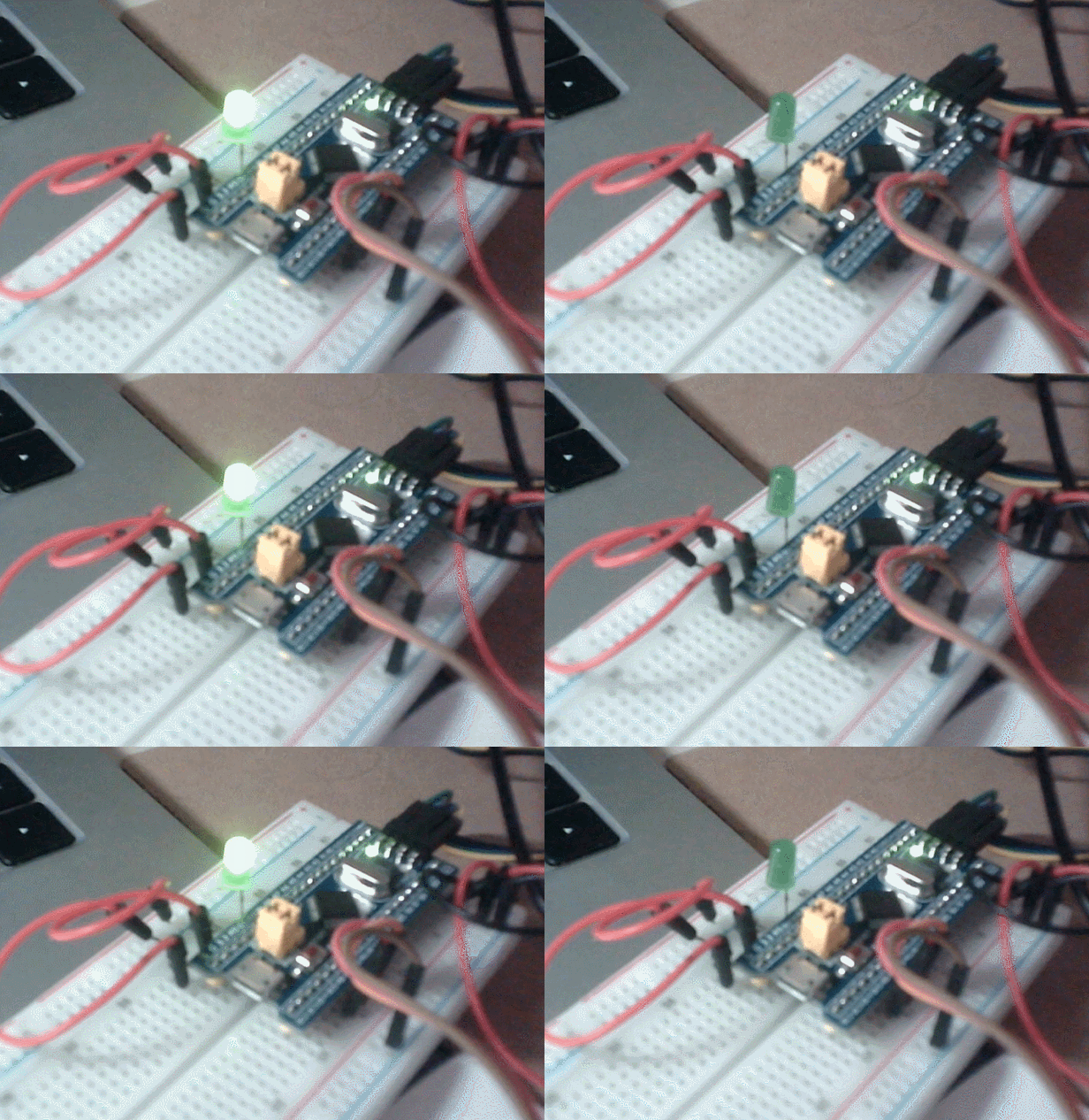
Experimental results

Application of PWM
Experimental requirements
Connect it, use the timer PWM mode, let the LED gradually brighten and fade out in the way of a breathing light, with a cycle of 1~2 seconds, and adjust it to a satisfactory effect. Use Keil virtual oscilloscope to observe the PWM output waveform.
Code
PWM.c
#include "stm32f10x.h" // Device header

void PWM_Init(void)
{<!-- -->
RCC_APB1PeriphClockCmd(RCC_APB1Periph_TIM2, ENABLE);
RCC_APB2PeriphClockCmd(RCC_APB2Periph_GPIOA, ENABLE);
\t
// RCC_APB2PeriphClockCmd(RCC_APB2Periph_AFIO, ENABLE);
//GPIO_PinRemapConfig(GPIO_PartialRemap1_TIM2, ENABLE);
//GPIO_PinRemapConfig(GPIO_Remap_SWJ_JTAGDisable, ENABLE);
\t
GPIO_InitTypeDef GPIO_InitStructure;
GPIO_InitStructure.GPIO_Mode = GPIO_Mode_AF_PP;
GPIO_InitStructure.GPIO_Pin = GPIO_Pin_0; //GPIO_Pin_15;
GPIO_InitStructure.GPIO_Speed = GPIO_Speed_50MHz;
GPIO_Init(GPIOA, & amp;GPIO_InitStructure);
\t
TIM_InternalClockConfig(TIM2);
\t
TIM_TimeBaseInitTypeDef TIM_TimeBaseInitStructure;
TIM_TimeBaseInitStructure.TIM_ClockDivision = TIM_CKD_DIV1;
TIM_TimeBaseInitStructure.TIM_CounterMode = TIM_CounterMode_Up;
TIM_TimeBaseInitStructure.TIM_Period = 100 - 1; //ARR
TIM_TimeBaseInitStructure.TIM_Prescaler = 720 - 1; //PSC
TIM_TimeBaseInitStructure.TIM_RepetitionCounter = 0;
TIM_TimeBaseInit(TIM2, & amp;TIM_TimeBaseInitStructure);
\t
TIM_OCInitTypeDef TIM_OCInitStructure;
TIM_OCStructInit( & amp;TIM_OCInitStructure);
TIM_OCInitStructure.TIM_OCMode = TIM_OCMode_PWM1;
TIM_OCInitStructure.TIM_OCPolarity = TIM_OCPolarity_High;
TIM_OCInitStructure.TIM_OutputState = TIM_OutputState_Enable;
TIM_OCInitStructure.TIM_Pulse = 0; //CCR
TIM_OC1Init(TIM2, & amp;TIM_OCInitStructure);
\t
TIM_Cmd(TIM2, ENABLE);
}

void PWM_SetCompare1(uint16_t Compare)
{<!-- -->
TIM_SetCompare1(TIM2, Compare);
}
main.c
#include "stm32f10x.h" // Device header
#include "Delay.h"
#include "OLED.h"
#include "PWM.h"

uint8_t i;

int main(void)
{<!-- -->
OLED_Init();
PWM_Init();
\t
while (1)
{<!-- -->
for (i = 0; i <= 100; i + + )
{<!-- -->
PWM_SetCompare1(i);
Delay_ms(5);
}
for (i = 0; i <= 100; i + + )
{<!-- -->
PWM_SetCompare1(100 - i);
Delay_ms(5);
}
}
}
Experimental results
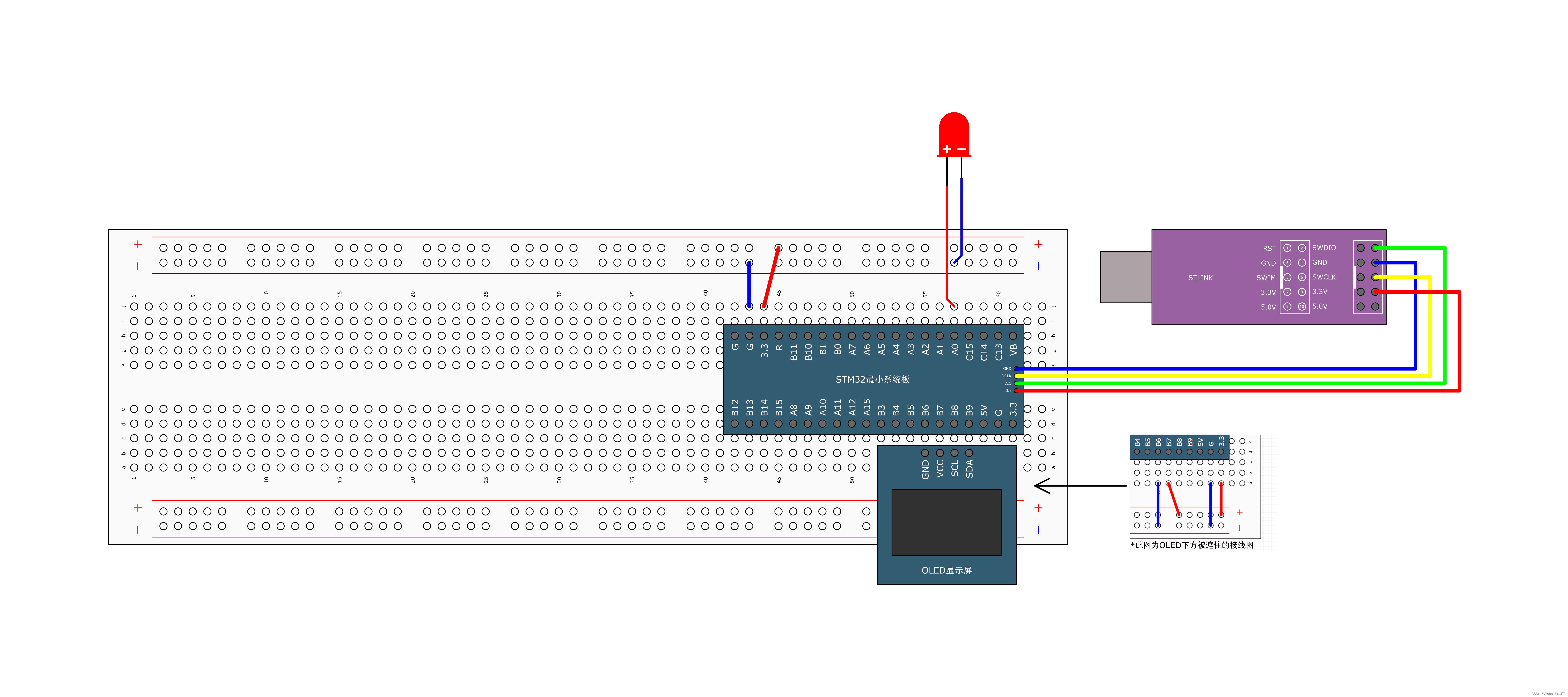
wiring:

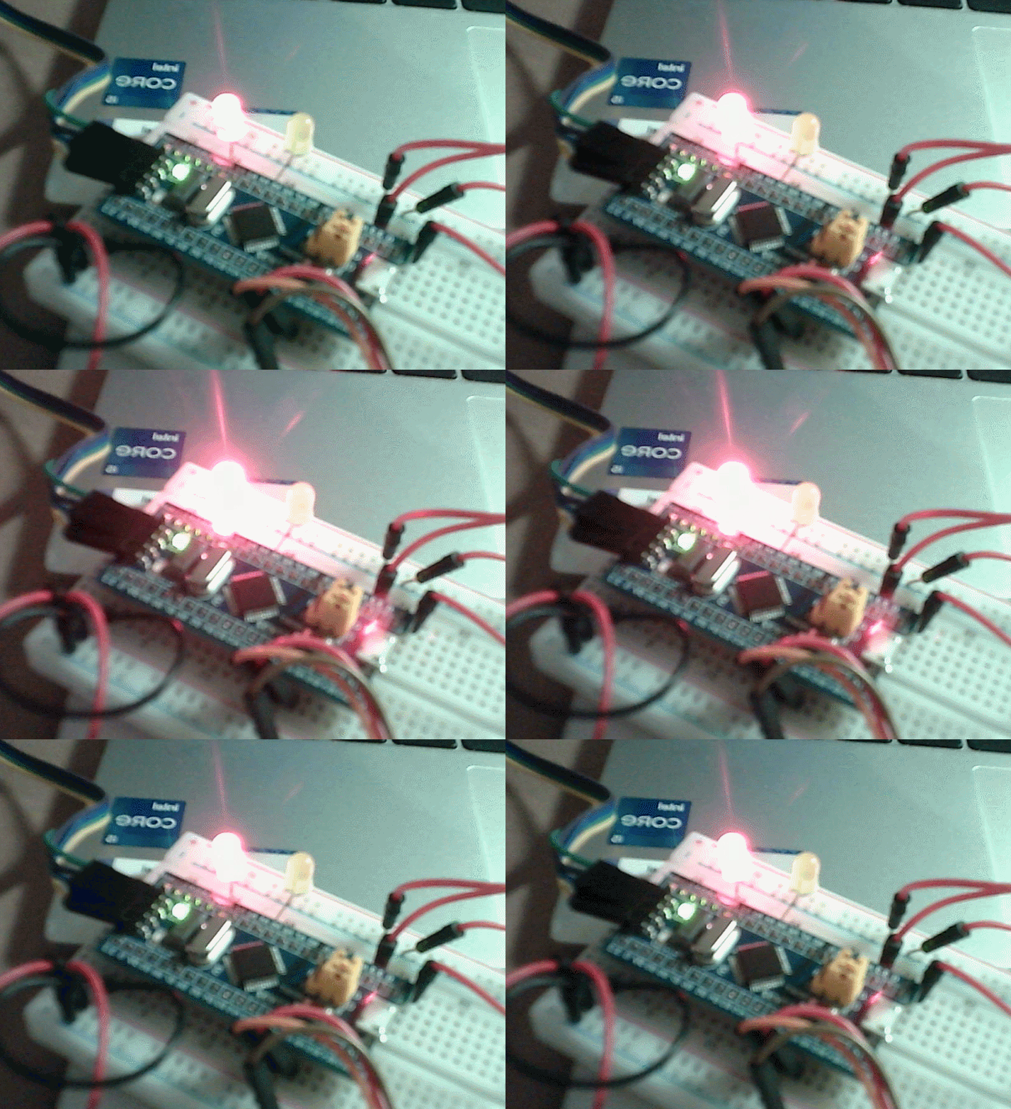
The effect after burning:

Use Keil virtual oscilloscope to observe the PWM output waveform
For the configuration of Keil virtual oscilloscope, see:
Link: https://blog.csdn.net/weixin_63019977/article/details/133749827
Select pin PA0:

It is marked as bit display and represented by a green line. The obtained waveform result is as shown in the figure below:

Summary
Before conducting the experiment, we need to understand the timer principle and pulse width modulation (PWM) generation method of STM32. Timers can implement timing and counting functions through counters and related registers, while PWM is a way to control circuits through pulse signals with different duty cycles.
In this experiment, we use a timer channel in Tim2~Tim5 of the STM32F103 series to connect the LED to the corresponding GPIO pin. First, using the timer counting method, by configuring the timer parameters and interrupt processing function, the LED can be turned on and off periodically at a frequency of 2 seconds.
Next, we use the PWM mode of the timer. By configuring the parameters of the timer and related registers, we can realize the LED gradually turning on and off in a breathing light manner. The adjustment cycle is 1 to 2 seconds, and you can adjust it to a satisfactory effect according to personal preferences. Through the Keil virtual oscilloscope, we can observe the PWM output waveform to verify the correctness of the PWM.
During the experiment, we need to carefully read the relevant STM32 timer and PWM mode documents to understand the configuration method of its registers and the writing of interrupt processing functions. At the same time, you need to be familiar with the use of Keil virtual oscilloscope in order to observe the waveform output.
Overall, this experiment can help us gain a deeper understanding of STM32’s timer principles and PWM generation methods, while also cultivating our ability to read documentation and debug. Through actual operations and observation of waveforms, we can better grasp and understand the working principles of timers and PWM, which provides a foundation and experience for subsequent projects and applications.
