STM32 timer application
1. Principle of timer
Timer of STM32F103 series:
- Timer functions: timing, input comparison, output capture, complementary output;
- Timer classification: basic timer, general timer, advanced timer;
- Timer resources: advanced timers (2 pcs) TIM1 and TIM8; general timers (4 pcs) TIM2/3/4/5; basic timers (2 pcs) TIM6 and TIM7;
- Basic timer classification:

5. Timer structure block diagram:

[Information reference: http://t.csdnimg.cn/B9098]
5.Working process
The 16-bit counter TIMx_CNT in the STM32F103 basic timer can only work in up-counting mode, and the auto-reload register stores the overflow value of the timer.
When the basic timer is working, the pulse counter TIMx_CNT starts from 0 and continuously counts up when triggered by the clock CK_CNT.
When the count value of the pulse counter TIMx_CNT equals the preset value saved in the automatic reload register TIMx_ARR (Auto Reload Register), an overflow event occurs, which can trigger an interrupt or DAC request. Then, the count value of the pulse counter TIMx_CNT is cleared and the upward counting starts again.
2. stm32 breathing light
[Requirement: Use Tim2~Tim5 of STM32F103 and a certain channel pin of the timer (multiplexed with the GPIOx pin, see the figure below), connect an LED, and use the timer counting mode to control the LED to periodically turn on at a frequency of 2s. On-off. ]
1Create a new project and select ACCESS TO MCU SELECTOR:

2 Select chip STM32F103C8T6

3 Configure SYS

4 Configure RCC

5Configure GPIO

6 Configure timers 2 and 3
Configure the timer’s clock source as the internal clock; the frequency division coefficient is 71; the up-counting mode, the counting period is 5000, and the automatic reload mode is enabled.
The frequency division coefficient is written as 71, but the system will automatically add 1 during processing, so the actual frequency division is 72. Since we generally configure the clock to 72MHZ, we get a clock of 1MHZ after dividing it by 72. With a 1MHZ clock, count 5000 times and get the time 5000/1000000=0.005 seconds. That is, timer 2 will generate a timed interrupt every 0.005 seconds.


7 Configure NVIC
Enable interrupts for timer 2 and timer 3

Generate timer 2 and timer 3 interrupt priority configuration code:

8 Configure USART1
Select Connectivity, click on USART1, and select Asynchronous communication in Mode.

9 Configure Clock Configuration

10 Configure Project Manager

3. KEIL configuration
The required main.c code is as follows:
/* USER CODE BEGIN Header */
/**
  *************************************************** ******************************
  * @file: main.c
  * @brief: Main program body
  *************************************************** ******************************
  *@attention
  *
  * Copyright (c) 2022 STMicroelectronics.
  * All rights reserved.
  *
  * This software is licensed under terms that can be found in the LICENSE file
  * in the root directory of this software component.
  * If no LICENSE file comes with this software, it is provided AS-IS.
  *
  *************************************************** ******************************
  */
/* USER CODE END Header */
/* Includes ----------------------------------------------- ------------------*/
#include "main.h"
#include "tim.h"
#include "usart.h"
#include "gpio.h"

/* Private includes -------------------------------------------------- ----------*/
/* USER CODE BEGIN Includes */

/* USER CODE END Includes */

/* Private typedef ----------------------------------------------- -------------*/
/* USER CODE BEGIN PTD */

/* USER CODE END PTD */

/* Private define -------------------------------------------------- ---------------*/
/* USER CODE BEGIN PD */
/* USER CODE END PD */

/* Private macro ----------------------------------------------- ---------------*/
/* USER CODE BEGIN PM */

/* USER CODE END PM */

/* Private variables -------------------------------------------------- -----------*/

/* USER CODE BEGIN PV */

/* USER CODE END PV */

/* Private function prototypes ------------------------------------------------ --*/
void SystemClock_Config(void);
static void MX_NVIC_Init(void);
/* USER CODE BEGIN PFP */

/* USER CODE END PFP */

/*Private user code--------------------------------------------- ----------*/
/* USER CODE BEGIN 0 */

/* USER CODE END 0 */

/**
  * @brief The application entry point.
  * @retval int
  */
  uint8_t hello[20]="hello windows!\r\
";
int main(void)
{
  /* USER CODE BEGIN 1 */

  /* USER CODE END 1 */

  /* MCU Configuration------------------------------------------------- ----------*/

  /* Reset of all peripherals, Initializes the Flash interface and the Systick. */
  HAL_Init();

  /* USER CODE BEGIN Init */

  /* USER CODE END Init */

  /* Configure the system clock */
  SystemClock_Config();

  /* USER CODE BEGIN SysInit */

  /* USER CODE END SysInit */

  /* Initialize all configured peripherals */
  MX_GPIO_Init();
  MX_TIM2_Init();
  MX_TIM3_Init();
  MX_USART1_UART_Init();

  /* Initialize interrupts */
  MX_NVIC_Init();
HAL_TIM_Base_Start_IT( & amp;htim2);
HAL_TIM_Base_Start_IT( & amp;htim3);

  /* USER CODE BEGIN 2 */

  /* USER CODE END 2 */

  /* Infinite loop */
  /* USER CODE BEGIN WHILE */
  while (1)
  {
    /* USER CODE END WHILE */

    /* USER CODE BEGIN 3 */
  }
  /* USER CODE END 3 */
}

/**
  * @brief System Clock Configuration
  * @retval None
  */
void SystemClock_Config(void)
{
  RCC_OscInitTypeDef RCC_OscInitStruct = {0};
  RCC_ClkInitTypeDef RCC_ClkInitStruct = {0};

  /** Initializes the RCC Oscillators according to the specified parameters
  * in the RCC_OscInitTypeDef structure.
  */
  RCC_OscInitStruct.OscillatorType = RCC_OSCILLATORTYPE_HSE;
  RCC_OscInitStruct.HSEState = RCC_HSE_ON;
  RCC_OscInitStruct.HSEPredivValue = RCC_HSE_PREDIV_DIV1;
  RCC_OscInitStruct.HSIState = RCC_HSI_ON;
  RCC_OscInitStruct.PLL.PLLState = RCC_PLL_ON;
  RCC_OscInitStruct.PLL.PLLSource = RCC_PLLSOURCE_HSE;
  RCC_OscInitStruct.PLL.PLLMUL = RCC_PLL_MUL9;
  if (HAL_RCC_OscConfig( & amp;RCC_OscInitStruct) != HAL_OK)
  {
    Error_Handler();
  }

  /** Initializes the CPU, AHB and APB buses clocks
  */
  RCC_ClkInitStruct.ClockType = RCC_CLOCKTYPE_HCLK|RCC_CLOCKTYPE_SYSCLK
                              |RCC_CLOCKTYPE_PCLK1|RCC_CLOCKTYPE_PCLK2;
  RCC_ClkInitStruct.SYSCLKSource = RCC_SYSCLKSOURCE_PLLCLK;
  RCC_ClkInitStruct.AHBCLKDivider = RCC_SYSCLK_DIV1;
  RCC_ClkInitStruct.APB1CLKDivider = RCC_HCLK_DIV2;
  RCC_ClkInitStruct.APB2CLKDivider = RCC_HCLK_DIV1;

  if (HAL_RCC_ClockConfig( & amp;RCC_ClkInitStruct, FLASH_LATENCY_2) != HAL_OK)
  {
    Error_Handler();
  }
}

/**
  * @brief NVIC Configuration.
  * @retval None
  */
static void MX_NVIC_Init(void)
{
  /* TIM2_IRQn interrupt configuration */
  HAL_NVIC_SetPriority(TIM2_IRQn, 0, 0);
  HAL_NVIC_EnableIRQ(TIM2_IRQn);
  /* TIM3_IRQn interrupt configuration */
  HAL_NVIC_SetPriority(TIM3_IRQn, 0, 0);
  HAL_NVIC_EnableIRQ(TIM3_IRQn);
}

/* USER CODE BEGIN 4 */
void HAL_TIM_PeriodElapsedCallback(TIM_HandleTypeDef *htim)
{
static uint32_t time_cnt =0;
static uint32_t time_cnt3 =0;
if(htim->Instance == TIM2)
{
if( + + time_cnt >= 400)
{
time_cnt =0;
HAL_GPIO_TogglePin(GPIOA,GPIO_PIN_0);
}
}
if(htim->Instance == TIM3)
{
if( + + time_cnt3 >= 1000)
{
time_cnt3 =0;
    HAL_UART_Transmit( & amp;huart1,hello,20,100000);
}
\t\t\t
}
}

/* USER CODE END 4 */
/**
  * @brief This function is executed in case of error occurrence.
  * @retval None
  */
void Error_Handler(void)
{
  /* USER CODE BEGIN Error_Handler_Debug */
  /* User can add his own implementation to report the HAL error return state */
  __disable_irq();
  while (1)
  {
  }
  /* USER CODE END Error_Handler_Debug */
}

#ifdef USE_FULL_ASSERT
/**
  * @brief Reports the name of the source file and the source line number
  * where the assert_param error has occurred.
  * @param file: pointer to the source file name
  * @param line: assert_param error line source number
  * @retval None
  */
void assert_failed(uint8_t *file, uint32_t line)
{
  /* USER CODE BEGIN 6 */
  /* User can add his own implementation to report the file name and line number,
     ex: printf("Wrong parameters value: file %s on line %d\r\
", file, line) */
  /* USER CODE END 6 */
}
#endif /* USE_FULL_ASSERT */

Burn to stm32 to get the breathing light:

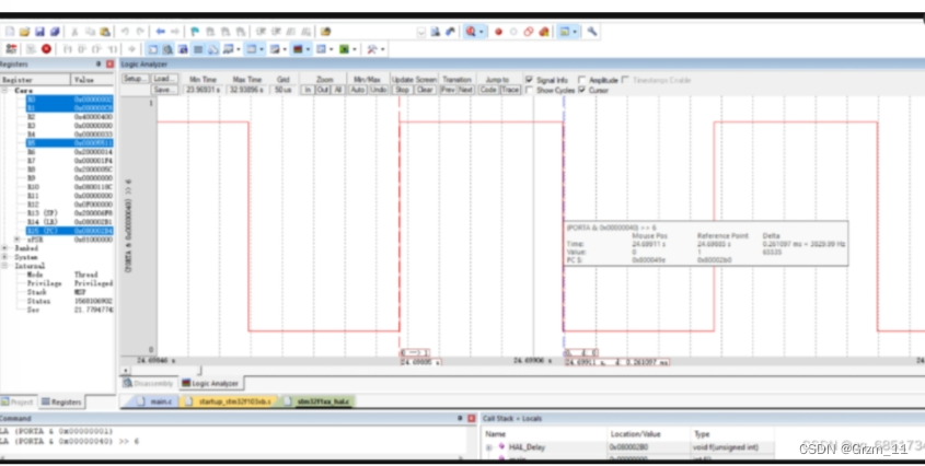
4. Observe the output waveform
[2. Connect it, use the timer pwm mode, let the LED gradually light up and turn off in the way of a breathing light, with a cycle of 1~2 seconds, and adjust it to a satisfactory effect. Use Keil virtual oscilloscope to observe the pwm output waveform. 】
Enter keil5 simulation:
In the Target interface, select the correct crystal oscillator size and use an 8MHz external crystal oscillator:
The output waveform is as follows:
R CODE END 6/
}
#endif / USE_FULL_ASSERT */
[External link pictures are being transferred...(img-t7K30Idk-1699196707232)] Burn to stm32 to get the breathing light: [External link pictures are being transferred...(img-NX2jbrgk-1699196707232)] #### 4. Observe the output waveform [2. Connect it, use the timer pwm mode, let the LED gradually light up and turn off in the way of a breathing light, with a cycle of 1~2 seconds, and adjust it to a satisfactory effect. Use Keil virtual oscilloscope to observe the pwm output waveform. 】 Enter keil5 simulation: In the Target interface, select the correct crystal oscillator size and use an 8MHz external crystal oscillator: The output waveform is as follows: