1. Communication principle of SPI
SPI can be used as both a master and a slave.
When acting as a host. MOSI, SCK, and CS are all used as outputs. And as a slave. MOSI, SCK, and CS are all used as input.
 So the SPI hardware circuit should implement such a function.
2. SPI block diagram of GD32/STM32
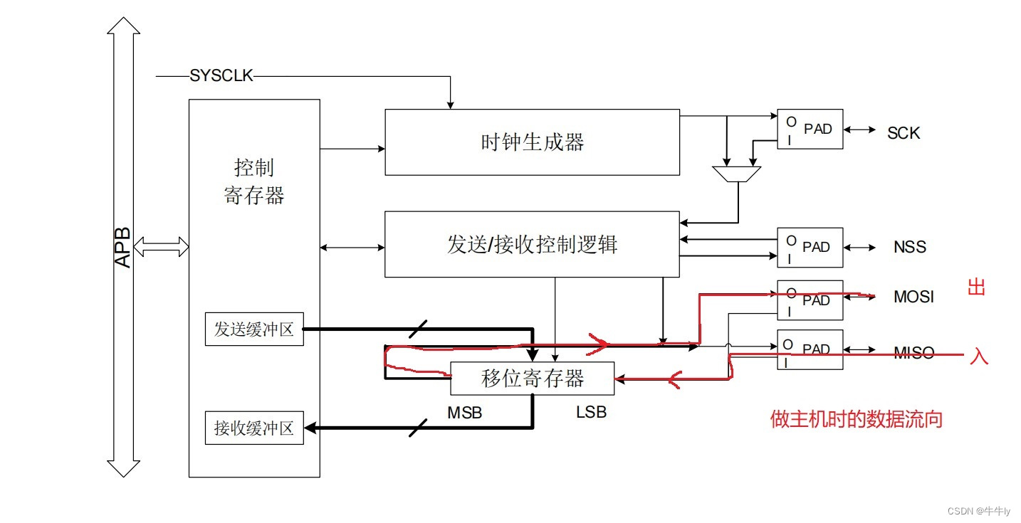
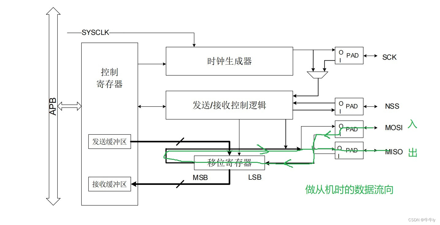
1. GD32 block diagram
The data flow direction of the host is as shown below:
The data flow direction of the slave is as shown below:
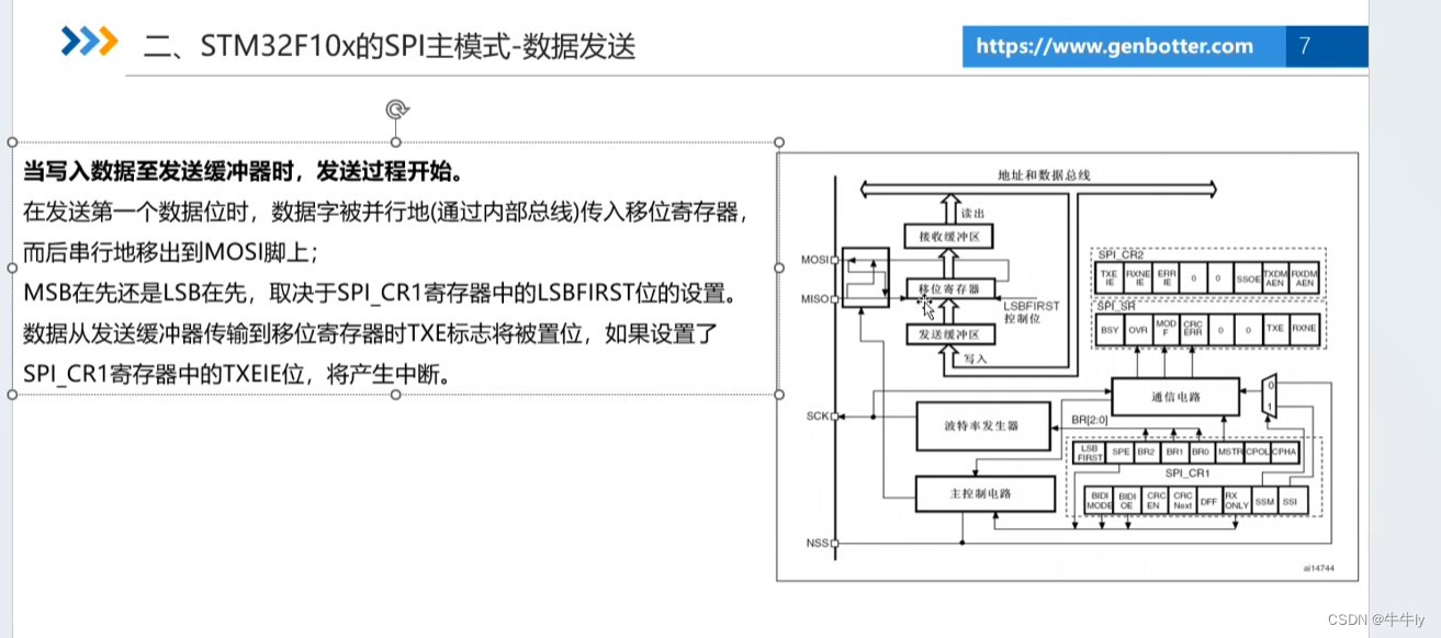
2. STM32 block diagram
The circuit is controlled through the configuration of some registers. It’s almost the same as GD32.
The higher the baud rate configuration, the faster the sampling. The speed of SPI is faster.

3. Introduction to SPI registers
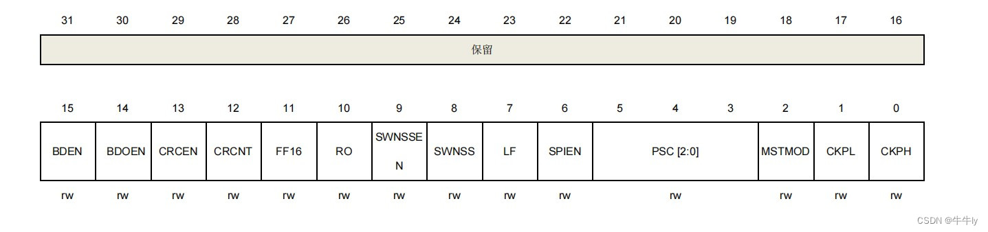
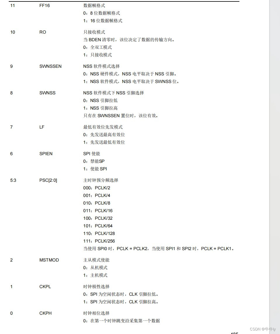
1. Control register 0 (SPI_CTL0)
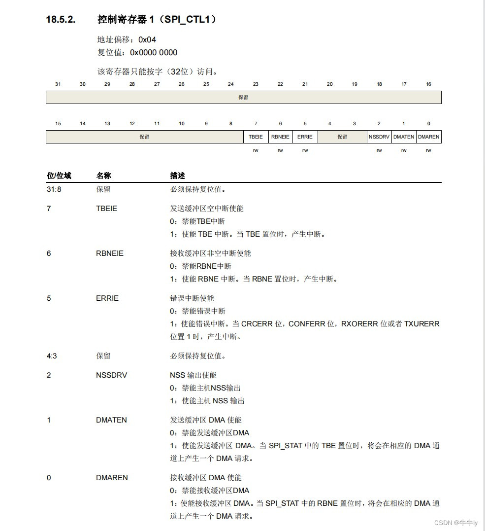
2. Control register 1 (SPI_CTL1)
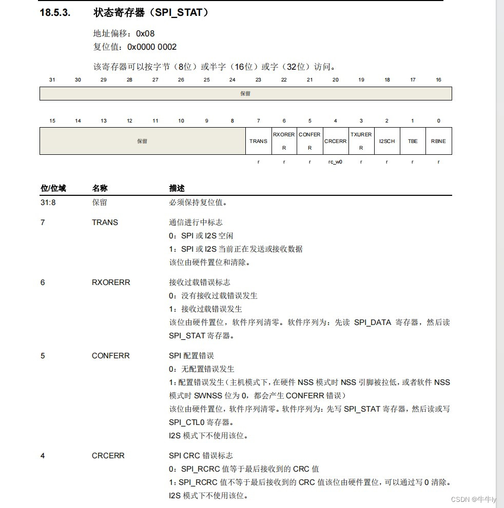
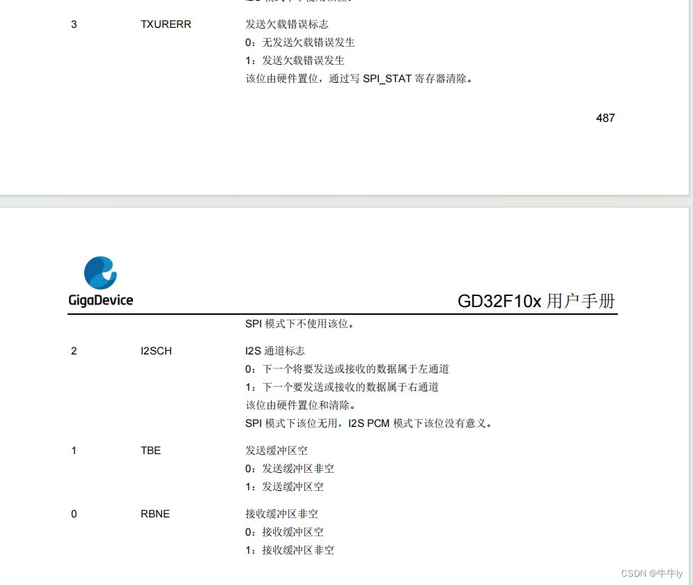
3. Status Register (SPI_STAT)
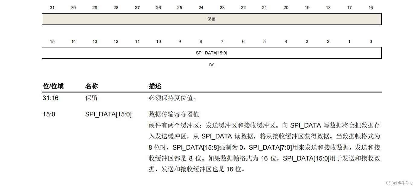
4. Data register (SPI_DATA)
4. SPI master mode configuration

1. Send data
First determine whether the sending host’s sending buffer is empty.

2. Receive data
Whether the receive data buffer is empty. If empty, wait, otherwise receive.
5. dome (hardware SPI access w25Q32)
NSS\SCK\MISO\MOSI corresponding PA4\PA5\PA6\PA7 pins.
1. Specific SPI configuration steps.
1. SPI clock is enabled, and the GPIO clock corresponding to SPI is enabled. Multiplexed clock enable.
2. SPI’s GOIP configuration.
3. SPI initialization configuration
4. SPI enable.
2. Code implementation
spi.h
#ifndef _SPI_H
#define _SPI_H

#include "gd32f10x.h"


void w25qxx_rcu_init(void);
void w25qxx_io_init(void);
void w25qxx_spi_init(void);

#endif
spi.c
#include "spi.h"

// Enable peripheral clock
void w25qxx_rcu_init(void)
{
rcu_periph_clock_enable(RCU_GPIOA); //Enable GPIOA clock
rcu_periph_clock_enable(RCU_AF); //Enable AF clock
rcu_periph_clock_enable(RCU_SPI0); //Enable SPI0 clock
}
\t
// Configure the IO port to reuse it as SPI0, PA4\PA5\PA6\PA7, NSS\SCK\MISO\MOSI
void w25qxx_io_init(void)
{
gpio_init(GPIOA, GPIO_MODE_IN_FLOATING, GPIO_OSPEED_50MHZ, GPIO_PIN_6); // MISO floating input
\t
gpio_init(GPIOA, GPIO_MODE_AF_PP, GPIO_OSPEED_50MHZ, GPIO_PIN_5 | GPIO_PIN_7); // SCK\MOSI multiplexed push-pull
\t
gpio_init(GPIOA, GPIO_MODE_OUT_PP, GPIO_OSPEED_50MHZ, GPIO_PIN_4);// NSS chip select port ordinary push-pull output
}
\t
// SPI0 initialization
void w25qxx_spi_init(void)
{
spi_parameter_struct spi_struct;
spi_struct.device_mode = SPI_MASTER; /*!< SPI master serves as the host*/
  spi_struct.trans_mode = SPI_TRANSMODE_FULLDUPLEX; /*!< SPI transfer type full duplex */
  spi_struct.frame_size = SPI_FRAMESIZE_8BIT; /*!< SPI frame size 8 bytes at a time */
  spi_struct.nss = SPI_NSS_SOFT; /*!< SPI NSS control by software software CS */
  spi_struct.endian = SPI_ENDIAN_MSB; /*!< SPI big endian or little endian transmit high byte first*/
  spi_struct.clock_polarity_phase = SPI_CK_PL_LOW_PH_1EDGE; /*!< SPI clock phase and polarity idle low level first edge for sampling*/
  spi_struct.prescale = SPI_PSC_8; /*!< SPI prescaler factor 8 frequency division*/
spi_init(SPI0, & amp;spi_struct);
}
w25qxx.h
#ifndef _W25QXX_SPI_H
#define _W25QXX_SPI_H

#include "gd32f10x.h"
#include "w25qxx_ins.h"
#include "gd32f10x_spi.h"

#define W25QXX_ID_1 1

#define W25QXX_SR_ID_1 1
#define W25QXX_SR_ID_2 2
#define W25QXX_SR_ID_3 3
void w25qxx_init(void);
void w25qxx_wait_busy(void);
uint8_t w25qxx_read_sr(uint8_t sregister_id); // Read status register
\t
void w25qxx_read(uint8_t *p_buffer, uint32_t read_addr, uint16_t num_read_bytes);

void w25qxx_write(uint8_t *p_buffer, uint32_t write_addr, uint16_t num_write_bytes);
void w25qxx_write_nocheck(uint8_t *p_buffer, uint32_t write_addr, uint16_t num_write_bytes); //
void w25qxx_write_page(uint8_t *p_buffer, uint32_t write_addr, uint16_t num_write_bytes); // page program

void w25qxx_erase_sector(uint32_t sector_addr);
void w25qxx_erase_chip(void);

void w25qxx_write_enable(void);
void w25qxx_write_disable(void);

void w25qxx_power_down(void);
void w25qxx_wake_up(void);

void w25qxx_cs_enable(uint8_t cs_id);
void w25qxx_cs_disable(uint8_t cs_id);
uint8_t w25qxx_swap(uint8_t byte_to_send);


#endif
w25qxx.c
#include "w25qxx.h"
#include "spi.h"

void w25qxx_init(void){
// Enable peripheral clock
w25qxx_rcu_init();
\t
// Configure the IO port to reuse it as SPI0, PA4\PA5\PA6\PA7, NSS\SCK\MISO\MOSI
w25qxx_io_init();
\t
// SPI0 initialization
w25qxx_spi_init();
//SPI enable
spi_enable(SPI0);
}


// If the BUSY bit of SR-1 is 1, wait until the BUSY bit is 0 and end the waiting.
void w25qxx_wait_busy(void){
while((w25qxx_read_sr(W25QXX_SR_ID_1) & amp; 0x01) == 0x01){
;
}
}

//Read status register
uint8_t w25qxx_read_sr(uint8_t sregister_id){
uint8_t command, result;
switch(sregister_id){
case W25QXX_SR_ID_1:
command = W25QXX_READ_STATUS_REGISTER_1;
break;
case W25QXX_SR_ID_2:
command = W25QXX_READ_STATUS_REGISTER_2;
break;
case W25QXX_SR_ID_3:
command = W25QXX_READ_STATUS_REGISTER_3;
break;
default:
command = W25QXX_READ_STATUS_REGISTER_1;
break;
}
\t
w25qxx_cs_enable(W25QXX_ID_1);
w25qxx_swap(command);
result = w25qxx_swap(0xFF);
w25qxx_cs_disable(W25QXX_ID_1);
\t
return result;
}

//Read flash data
// *p_buffer The storage location of the data read back
void w25qxx_read(uint8_t *p_buffer, uint32_t read_addr, uint16_t num_read_bytes){
uint16_t i;
\t
w25qxx_cs_enable(W25QXX_ID_1);
\t
w25qxx_swap(W25QXX_READ_DATA); //Send the command to read data
w25qxx_swap(read_addr >> 16); //Send 24bit address
w25qxx_swap(read_addr >> 8);
w25qxx_swap(read_addr);
\t
for(i=0; i < num_read_bytes; i + + ){
p_buffer[i] = w25qxx_swap(0xFF);
}
\t
w25qxx_cs_disable(W25QXX_ID_1);
}

//
uint8_t W25QXX_Buffer[4096]; //Used to store bytes read from sector
void w25qxx_write(uint8_t *p_buffer, uint32_t write_addr, uint16_t num_write_bytes){
uint32_t sec_num;
uint16_t sec_remain;
uint16_t sec_off;
uint16_t i;
\t
sec_num = write_addr / 4096; //The location to be written is on the sec_num sector
sec_off = write_addr % 4096;
\t
sec_remain = 4096 - sec_off;
\t
if(num_write_bytes <= sec_remain){
w25qxx_read(W25QXX_Buffer, sec_num * 4096, 4096); //Read the sector data
\t\t
for(i = 0; i < sec_remain; i + + ){
if(W25QXX_Buffer[i + sec_off] != 0xFF) //Indicates that the i + sec_off bit of this sector has not been erased
break;
}
\t\t
if(i < sec_remain){ // sector is not erased
w25qxx_erase_sector(sec_num * 4096);
for(i = 0; i < sec_remain; i + + ){
W25QXX_Buffer[i + sec_off] = p_buffer[i];
}
w25qxx_write_nocheck(W25QXX_Buffer, sec_num * 4096, 4096);
}else{ // The sec_remain part of the sector is erased
w25qxx_write_nocheck(p_buffer, write_addr, num_write_bytes);
}
}else{
w25qxx_read(W25QXX_Buffer, sec_num * 4096, 4096); //Read the sector data
\t\t
for(i = 0; i < sec_remain; i + + ){
if(W25QXX_Buffer[i + sec_off] != 0xFF) //Indicates that the i + sec_off bit of this sector has not been erased
break;
}
\t\t
if(i < sec_remain){ // sector is not erased
w25qxx_erase_sector(sec_num * 4096);
for(i = 0; i < sec_remain; i + + ){
W25QXX_Buffer[i + sec_off] = p_buffer[i];
}
w25qxx_write_nocheck(W25QXX_Buffer, sec_num * 4096, 4096);
}else{ // The sec_remain part of the sector is erased
w25qxx_write_nocheck(p_buffer, write_addr, sec_remain);
}
\t\t
write_addr + = sec_remain;
p_buffer + = sec_remain;
num_write_bytes -= sec_remain;
w25qxx_write(p_buffer, write_addr, num_write_bytes);
}
\t\t
//Determine whether the read data is all 0xFF
;//Whether the sector is deleted?
//Determine whether to cross page
}

// Make sure the sector is deleted before calling
void w25qxx_write_nocheck(uint8_t *p_buffer, uint32_t write_addr, uint16_t num_write_bytes){
uint16_t page_remain = 256 - write_addr % 256;
\t
if(num_write_bytes <= page_remain){
w25qxx_write_page(p_buffer, write_addr, num_write_bytes);
}else{
w25qxx_write_page(p_buffer, write_addr, page_remain);
p_buffer + = page_remain;
write_addr + = page_remain;
num_write_bytes -= page_remain;
w25qxx_write_nocheck(p_buffer, write_addr, num_write_bytes);
}
}

// page program
// Call this function to write content on a certain page while ensuring that there is no cross-page writing.
void w25qxx_write_page(uint8_t *p_buffer, uint32_t write_addr, uint16_t num_write_bytes){
uint16_t i;
\t
w25qxx_write_enable();
\t
w25qxx_cs_enable(W25QXX_ID_1);
w25qxx_swap(W25QXX_PAGE_PROGRAM);
w25qxx_swap(write_addr >> 16); //Send 24bit address
w25qxx_swap(write_addr >> 8);
w25qxx_swap(write_addr);
\t
for(i = 0; i < num_write_bytes; i + + ){
w25qxx_swap(p_buffer[i]);
}
w25qxx_cs_disable(W25QXX_ID_1);
\t
w25qxx_wait_busy();
}

void w25qxx_erase_sector(uint32_t sector_addr){
w25qxx_write_enable();
\t
w25qxx_cs_enable(W25QXX_ID_1);
w25qxx_swap(W25QXX_SECTOR_ERASE_4KB);
w25qxx_swap(sector_addr >> 16);
w25qxx_swap(sector_addr >> 8);
w25qxx_swap(sector_addr);
w25qxx_cs_disable(W25QXX_ID_1);
\t
w25qxx_wait_busy();
}

void w25qxx_erase_chip(void){
w25qxx_write_enable();
\t
w25qxx_cs_enable(W25QXX_ID_1);
w25qxx_swap(W25QXX_CHIP_ERASE);
w25qxx_cs_disable(W25QXX_ID_1);
\t
w25qxx_wait_busy();
}

void w25qxx_write_enable(void){
w25qxx_cs_enable(W25QXX_ID_1);
w25qxx_swap(W25QXX_WRITE_ENABLE);
w25qxx_cs_disable(W25QXX_ID_1);
}

void w25qxx_write_disable(void){
w25qxx_cs_enable(W25QXX_ID_1);
w25qxx_swap(W25QXX_WRITE_DISABLE);
w25qxx_cs_disable(W25QXX_ID_1);
}

// low battery sleep
void w25qxx_power_down(void){
w25qxx_cs_enable(W25QXX_ID_1);
w25qxx_swap(W25QXX_POWER_DOWN);
w25qxx_cs_disable(W25QXX_ID_1);
}

// wake up
void w25qxx_wake_up(void){
w25qxx_cs_enable(W25QXX_ID_1);
w25qxx_swap(W25QXX_RELEASE_POWER_DOWN_HPM_DEVICE_ID);
w25qxx_cs_disable(W25QXX_ID_1);
}

/*
brief: enable chip select pin cs
cs_id: The serial number of the cs pin, that is, which w25qxx flash
*/
void w25qxx_cs_enable(uint8_t cs_id){
switch(cs_id){
case W25QXX_ID_1:
gpio_bit_reset(GPIOA, GPIO_PIN_4);
break;
default:
break;
}
}

void w25qxx_cs_disable(uint8_t cs_id){
switch(cs_id){
case W25QXX_ID_1:
gpio_bit_set(GPIOA, GPIO_PIN_4);
break;
default:
break;
}
}

/*
Master-slave data exchange
*/
uint8_t w25qxx_swap(uint8_t byte_to_send){
while(spi_i2s_flag_get(SPI0, SPI_FLAG_TBE) == RESET){ // Wait for the SPI transmit buffer to be empty
;
}
spi_i2s_data_transmit(SPI0, byte_to_send); // Put data into the generation buffer
while(spi_i2s_flag_get(SPI0, SPI_FLAG_TRANS) == SET){ // Wait for the communication to end
;
}
\t
while(spi_i2s_flag_get(SPI0, SPI_FLAG_RBNE) == RESET){ // Wait for the SPI receive buffer to be non-empty
;
}
return spi_i2s_data_receive(SPI0); /* Return the received data (take it out from the receive buffer) */
}