Directory
Introduction to Linear Rendering Components
Introduction to Line Renderer Components for Drawing Lines
Introduction to drawing trailing Trail Renderer components
Application 1: Draw line segments using Line Renderer
Application 1 implementation: use system tools or custom tools to draw line segments
Application 2: Trail Renderer simply makes bullet trailing effects
Application 3: Draw a circle using LineRenderer (line segment approximation)
Introduction to Linear Rendering Components
The Line Renderer linear rendering component is used to render line segments in 3D, such as the laser gate damage done in the mini-game before, and the Line Renderer is used on the VR handle.
The Trail Renderer is also used to render line segments, and is used to add a high-speed motion trail effect to objects.
This article mainly records the use of Line Renderer, Trail Renderer components and APIs, the method of using them to draw line segments, and builds a collection of tools to store these practical tools, so that they can be used at any time in subsequent development.
Drawing lines Line Renderer component introduction
Line Renderer is a line that uses vertices to control the rendering size and position, and the number and coordinates of vertices can also be controlled. For the official Line Renderer component introduction, please see Line Renderer component – Unity Manual (unity3d.com)
Among them, the more commonly used options are width, Materials, etc., and other settings are generally controlled by scripts.
width controls the width of the line, and multiple nodes can be set to make the lines vary in width everywhere.


Materials control the line material, if not added, only pink will be displayed. Of course this can also be changed in the script.

Commonly used APIs for Line Renderer are:
positionCount: Set the number of points of the line segment;
SetPosition(int index, Vector3[] position): Add the position of the point (the subscript of the point, the position of the point);
startWidth, endWidth: the width of the start and end points;
material.Color: Ray material color
Introduction to Drawing Trail Renderer Components
The Trail Renderer component is very similar to the Line Renderer component. It can be hung on an object to make it have a trailing effect. Generally, the width can be set to be wider at the front and narrower at the back, for a more high-speed feeling:

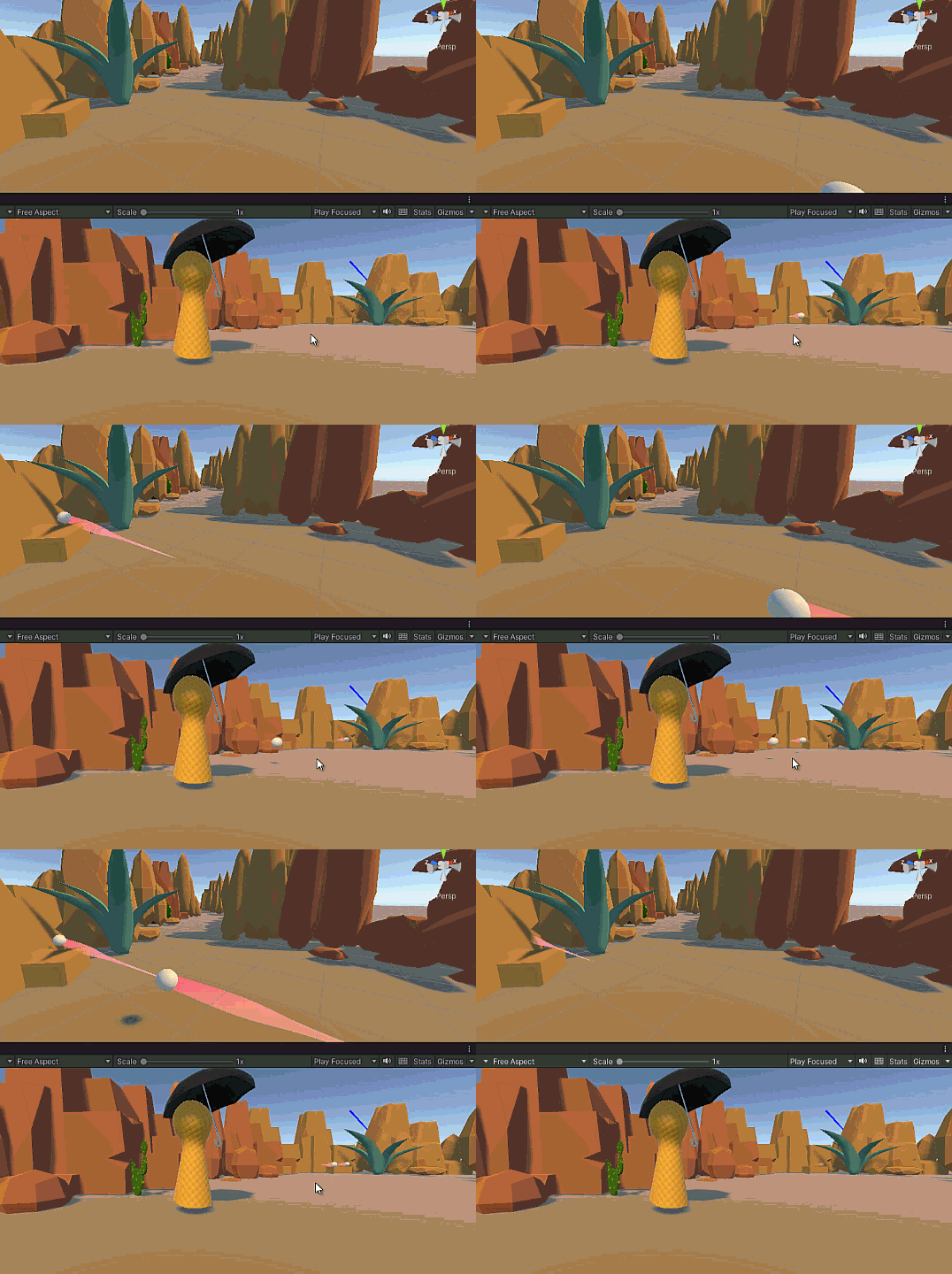
For other settings, please refer to the official document: Trail Renderer component – Unity Manual (unity3d.com), and you can use the API method to set in the script. The trailing effect is shown in the following figure:

Application 1: Use Line Renderer to draw line segments
Create a toolkit Tools.cs, set it as a static Statics class, the code is as follows:
//Static tool class
public static class Tools
{
    //Use LineRenderer to draw a line segment, method 1 (new line segment)
    public static LineRenderer DrawLine(Transform transform, Vector3 start, Vector3 end, Color color = default(Color),
        float width = 0.1f)
    {//DrawLine (set parent object, line segment start point, end point, color, width)
        GameObject gameObject = new GameObject(); //Create a new object in the field
        gameObject.transform.SetParent(transform); //Place this object under the parent object
        gameObject.name = "Line"; //Name the object
        LineRenderer line = gameObject.AddComponent<LineRenderer>(); //hang the LineRenderer component
        line.useWorldSpace = true; // set the line segment to world coordinates
        line.material = Resload.Instance.LoadAsset<Material>("line"); //Load the material named line from Resource
        line.SetVertexCount(2); //Set the number of vertices, 2, start point, end point
        line.SetWidth(width, width); //Set the width of the first vertex and the width of the second vertex
        line.material.SetColor("_Color", color); //This color is the color of the material, which is an attribute in the Material class
                                                   //What is modified here is the color attribute of the line material under the Resource folder
        line.startColor = color; //Set the start color and end color
        line.endColor = color; //can have a gradient effect, of course it can also be consistent
        line.SetPosition(0, start);//Set the starting and ending positions
        line. SetPosition(1, end);
        return line;
    }

    //Use LineRenderer to draw line segments, method 2 (modify existing line segments)
    public static LineRenderer DrawLine(Transform transform, LineRenderer line, Vector3 start, Vector3 end, Color color=default(Color), float width = 0.1f)
    {//DrawLine (set the parent object, provide a line segment for modification, the line segment start point, end point, color, width)
        if(line==null)
        {//First judge whether there is a line segment, if not, use method 2 to create a new one
            return DrawLine(transform,start,end,color,width);
        }
        //If the line segment already exists, modify the line segment attribute according to the following settings, which is the same as the setting method of method 1
        line. useWorldSpace = false;
        line. SetVertexCount(2);
        line. SetWidth(width, width);
        line.material.SetColor("_Color", color);
        line.startColor = color;
        line.endColor = color;
        line. SetPosition(0, start);
        line. SetPosition(1, end);
        return line;
    }

}
Here are 2 methods for drawing line segments. The first method is to create a new line segment, including creating a new object in the field and mounting the Line Renderer component. The second method is to modify the object that has already mounted the Line Renderer component. If there is a need to set more complex line segments, it can be defined in more detail.
Application 1 implementation: use system tools or custom tools to draw line segments
Create a new empty node line in the field, and mount a script line.cs (with any name). However, the position of this line node will affect the line segment drawn later, because the line segment is used as its child node. The script of line.cs only needs to be in Start() as follows
void Start()
    {
        //Use Unity's own Debug line tool
        Debug.DrawLine(transform.position,transform.position + transform.forward*10,Color.green,100);
        Debug.DrawRay(transform.position, transform.forward, Color.red, 100);

        //Use the Tools tool set to draw a line segment
        Tools.DrawLine(transform, transform.position, transform.position + transform.forward * 10, Color.blue, 0.1f);
    }
Here first try to use the drawing tool Debug.DrawLine that comes with Unity. Its definition is as follows, and the parameters passed are relatively small.
public static void DrawLine(Vector3 start, Vector3 end, Color color, float duration){}
* Note: When using static (static) classes, static methods, and static variables, it can only be called when the class is called (Tools.DrawLine()), instead of calling it through “object. method” after the new object .
The result of the operation is as follows:

Application 2: Trail Renderer makes simple bullet trailing effect
On the bullet prefab that has been done before, add Component directly, add the Trail Renderer component, and simply set the color, width, shadow and other parameters according to the needs to achieve the following effects:

Application 3: Use LineRenderer to draw a circle (line segment approximation)
Make a tool first, and add the following DrawCircle() method to the Tools.cs toolset:
 //Use LineRenderer to draw a line segment approaching a circle
    public static void DrawCircle(GameObject go, float xRadius, float yRadius, float zRadius,
        int number, float width,Color color = default(Color))
    {//Drawing a circle object, the radius in the x/y/z direction, the number of line segments, width, color
        if(!go. GetComponent<LineRenderer>())
        {
            go.AddComponent<LineRenderer>();
        }
        LineRenderer line=go. GetComponent<LineRenderer>();
        line.positionCount = number + 1;//5 lines have 6 vertices
        line.useWorldSpace = false; //Use local coordinates
        line.material = Resload.Instance.LoadAsset<Material>("line");
        line.material.SetColor("_Color", color);
        line. SetWidth(width, width);
        float x,y,z;
        float angle = 0; //Set the initial angle of drawing a circle (line) to 0, and turn an angle angle for each drawing until it reaches 360 degrees
        for(int i=0; i<line. positionCount; i ++ )
        {
            x = Mathf.Sin(Mathf.Deg2Rad * angle) * xRadius;
            y = Mathf.Cos(Mathf.Deg2Rad * angle) * yRadius;
            z=Mathf.Cos(Mathf.Deg2Rad*angle) * zRadius;
            line.SetPosition(i, new Vector3(x, y, z)); //Set the coordinates of each vertex of the line
            angle + = (360f / number);
        }
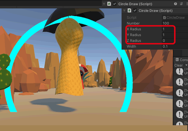
Use it on the protagonist (hang the following CircleDraw.cs on the protagonist):
public class CircleDraw : MonoBehaviour
{
    public int number; //Number of lines forming a circle
    public float xRadius;
    public float yRadius;
    public float zRadius;
    public float width;
    void Start()
    {
        Tools.DrawCircle(transform.gameObject, xRadius, yRadius, zRadius, number, width, Color.cyan);
    }
}
The effect is as follows:


