Directory
- 1. I2C bus protocol
-
- 1.1. Introduction to I2C
- 1.2. Hardware I2C
- 1.3. Protocol layer
-
- 1.3.1 I2C communication composite format
- 1.3.2 Start and stop signals of communication
- 1.3.3 Data validity
- 1.3.4 Address and data direction
- 1.3.5 Response
- 2. IIC protocol reads temperature and humidity data
-
- 2.1 Experimental content and AHT20
- 2.2 CubeMX configuration
-
- 2.2.1 System clock (RCC configuration)
- 2.2.2 SYS configuration
- 2.2.3 USART1 configuration
- 2.2.4 GPIO configuration
- 2.2.5 I2C1 configuration
- 2.2.6 NVIC configuration
- 2.2.7 Clock configuration
- 2.2.8 Generate project
- 2.2 Keil implementation
-
- 2.2.1 Add module code file
- 2.2.2 Change code main.c
- 3. Experimental results
-
- 3.1 Keil compilation results
- 3.2 FlyMCU burning results
- 3.3 Physical connection
- 3.4 Operational effect
- AHT20 manual and header files used
1. I2C bus protocol
1.1, Introduction to I2C
The I2C protocol has fewer pins, simple hardware implementation, and strong scalability. It does not require external transceiver devices such as USART, CAN and other communication protocols. It is now widely used for communication between multiple integrated circuits (ICs) in the system.
For communication protocols, we also
To understand it in a layered manner, the most basic thing is to divide it into the physical layer and the protocol layer. The physical layer specifies that communication systems have
The characteristics of mechanical and electronic functional parts ensure the transmission of original data in physical media. The protocol layer mainly specifies communication logic.
Unify the data packaging and unpacking standards for both sending and receiving parties. To put it simply, the physical layer stipulates whether we use mouth or body to communicate.
The protocol layer stipulates whether we should communicate in Chinese or English.
1.2, Hardware I2C
Common I2C communication systems:

Its physical layer has the following characteristics:
(1) It is a bus that supports devices. “Bus” refers to a signal line shared by multiple devices. In an I2C communication bus, multiple I2C communication devices can be connected, supporting multiple communication masters and multiple communication slaves.
(2) An I2C bus uses only two bus lines, a bidirectional serial data line (SDA) and a serial clock line (SCL). The data line is used to represent data, and the clock line is used to synchronize data transmission and reception.
(3) Each device connected to the bus has an independent address, and the host can use this address to access different devices.
(4) The bus is connected to the power supply through a pull-up resistor. When the I2C device is idle, it will output a high-impedance state. When all devices are idle and all output a high-impedance state, the pull-up resistor will pull the bus to a high level.
(5) When multiple hosts use the bus at the same time, in order to prevent data conflicts, arbitration will be used to determine which device will occupy the bus.
(6) It has three transmission modes: the standard mode transmission rate is 100kbit/s, the fast mode is 400kbit/s, and the high-speed mode can reach 3.4Mbit/s. However, most I2C devices currently do not support high-speed mode.
1.3, Protocol Layer
The I2C protocol defines communication start and stop signals, data validity, response, arbitration, clock synchronization and address broadcast.
1.3.1 I2C communication composite format

1.3.2 Communication start and stop signals

1.3.3 Data validity

1.3.4 Address and data direction

1.3.5 Response

2. IIC protocol to read temperature and humidity data
2.1 Experimental content and AHT20
Experimental content: Use STM32F103 to complete the data collection of the AHT20 temperature and humidity sensor based on the I2C protocol, and output the collected temperature-humidity values through the serial port. The temperature and humidity data are collected every 2 seconds and sent to the host computer (win10) through the serial port.
AHT20: Temperature and humidity sensor in standard I2C format
AHT20 scope of work
As can be seen from the figure below, the AHT20 has the best effect in measuring the temperature in the air when it works between 20°C and 60°C, and the sensor needs to be in full contact with the air.

AHT20 interface definition

Temperature and humidity conversion formula
Relative humidity RH can be calculated based on the relative humidity signal SRH output by the SDA through the following formula (the result is expressed in %RH):

Temperature T can be calculated by substituting the temperature output signal ST into the following formula (the result is expressed in temperature ℃):

There are also electrical features in the AHT20 product manual, including input and output features, sending commands, etc., which may be used when writing code or standard libraries for experimental registers, but the HAL library I use does not use these, so they will not be shown here. , can be found in the link
2.2 CubeMX configuration
2.2.1 System clock (RCC configuration)

2.2.2 SYS configuration

2.2.3 USART1 configuration

2.2.4 GPIO configuration

2.2.5 I2C1 configuration
Click ADD to add and select RX and TX

2.2.6 NVIC configuration

2.2.7 Clock configuration

2.2.8 Generate project


Then click GENERATE CODE in the upper right corner to generate the keil file
2.2 Keil implementation
2.2.1 Add module code file
Copy the AHT20-21_DEMO_V1_3.h and AHT20-21_DEMO_V1_3.c files of the module to the AHT20 folder under MDK-ARM. If there is no such folder, you need to create a new one


Add files to project

**Add the AHT20 folder just now to the Include Path here


2.2.2 Change code main.c
1. Redirect output function based on HAL library
#include<stdio.h>
int fputc(int ch, FILE *f)

{<!-- -->

  HAL_UART_Transmit( & amp;huart1, (uint8_t *) & amp;ch, 1, 0xffff);

  return ch;

}
2. Add the header file of AHT20
#include "AHT20-21_DEMO_V1_3.h"
3. The main function to implement the function: add the following code under the while loop
 printf("start read...\r\
");
    /* USER CODE END WHILE */
AHT20_Read_CTdata(CT_data);//No CRC check, directly read the temperature and humidity data of AHT20
HAL_Delay(1500);//Delay waiting for this read
c1 = CT_data[0]*1000/1024/1024; //Calculate the humidity value c1 (enlarged 10 times)
t1 = CT_data[1]*2000/1024/1024-500;//Calculate the temperature value t1 (enlarged 10 times)
printf("temperature:%d%d.%d ",t1/100,(t1/10) ,t1 );
printf("humidity:%d%d.%d\r\
",c1/100,(c1/10) ,c1 );
printf("waiting next...\r\
");
printf("\
");
HAL_Delay(500);//Delay 0.5s to wait for the next measurement
    /* USER CODE BEGIN 3 */
3. Experimental results
3.1 Keil compilation results

3.2 FlyMCU burning results
You need to set boot0 to 0 before programming. When using the serial port to transmit data, set boot0 to 1 and press the reset button.

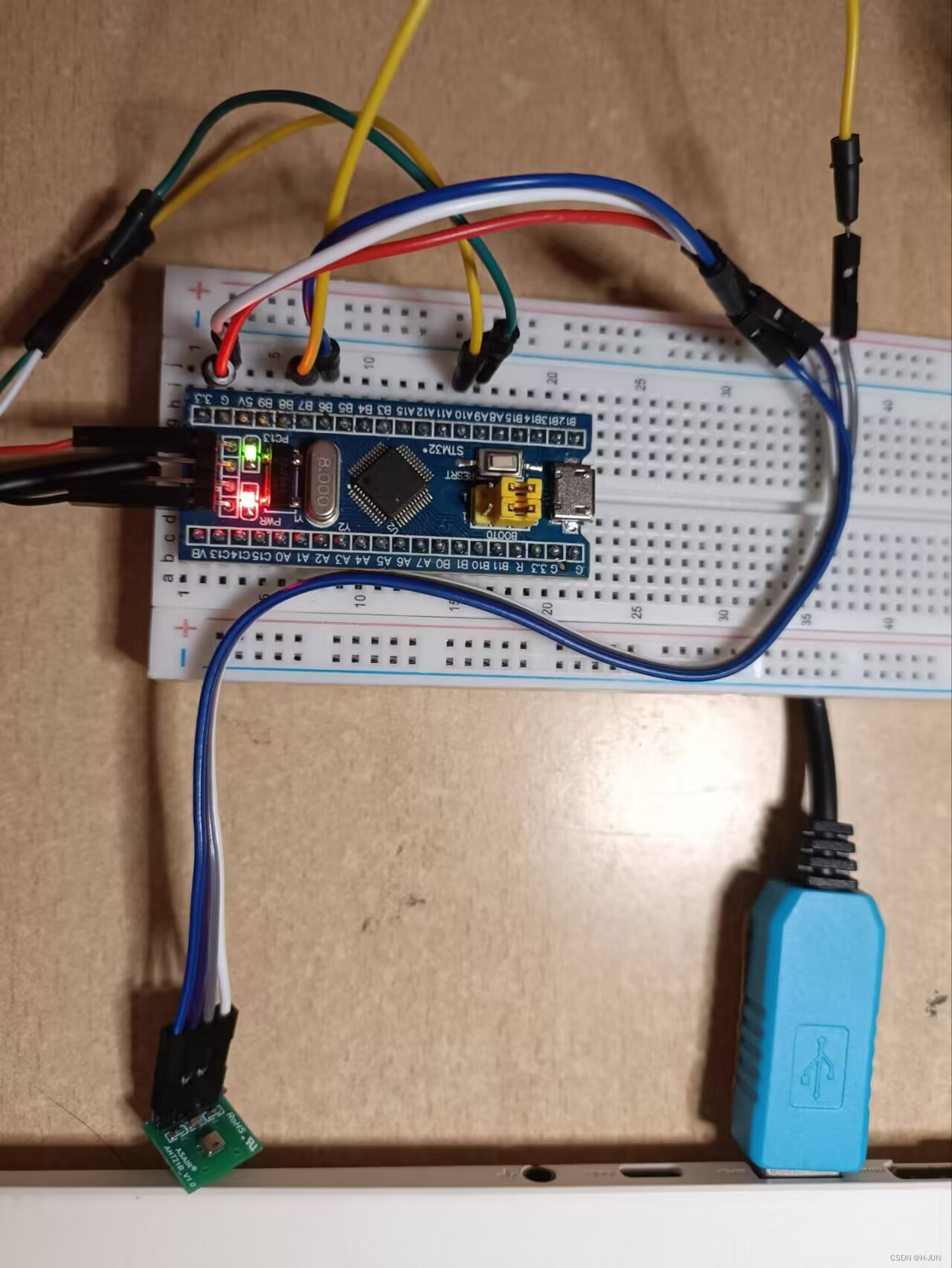
3.3 Physical connection
The on-chip pins are as shown in the figure. The pins correspond to the pin connections of the module as shown in the figure.

| Chip | AHT20 | UAB20 to TTL |
|---|---|---|
| PA9 (TXD) | White line (RXD) | |
| PA10 (RXD) | Green Line (TXD) | |
| PB6 (SCL) | SCL | |
| PB7 (SDA) | SDA |
3.4 Operation effect
AHT20 manual and header files used
Link: https://pan.baidu.com/s/1cExUzq0cE4S6gmsqplPxGw?pwd=8ruc
Extraction code: 8ruc