PWM breathing light based on STM32 standard library
Article directory
- PWM breathing light based on STM32 standard library
-
- 1. Introduction to STM32 timing function
- 2. Introduction to PWM functions
- 3. Create project
- 4. Realization of LED flashing and extinguishing regularly
-
- 4.1 Code ideas
- 4.2 Configuration code
- 4.3 Burning results
- 5. PWM configuration function analysis
-
- 5.1 Built-in clock enable
- 5.2 Configure time base unit
- 5.3 Enable update interrupt
- 5.4 Configure GPIO and start the timer
- 5.5 Output comparison function
- 5.6 Header files and final functions of C files
- 6. Analysis of PWM main function writing
-
- 6.1 Code ideas
- 6.2 Main function code
- 7. Burning results and waveform observation
- 8. Summary
- 9. Reference
1. Introduction to STM32 timing function
TIM (Timer) timer is a high-precision hardware device used for counting and timing. It contains a time base unit with a 16-bit counter, prescaler and automatic reload register, which can accurately count the input clock. When the count value reaches the set value, the timer will trigger an interrupt to perform the corresponding operation. This timer has the advantages of high precision and long timing time, so it is widely used in many embedded systems.
Depending on the complexity and application scenarios, TIM timers are divided into three types: advanced timers, general timers and basic timers.

The advanced timer has the highest complexity. It not only has basic timing interrupt functions, but also includes internal and external clock source selection, input capture, output comparison, encoder interface, master-slave trigger mode and other functions. This timer is suitable for application scenarios that require high accuracy and complexity, such as high-precision timing and complex timing control.
Universal timers are suitable for most application scenarios. It has basic scheduled interrupt functions, and you can also choose to use some other functions as needed. This timer is of moderate complexity and can meet the needs of most applications.
The basic timer is the simplest one, it only has basic timer interrupt function. This timer has the lowest complexity, so it is suitable for some simple application scenarios, such as timestamp recording.
In STM32, the clock is mainly divided into internal clock mode, external clock mode and encoder mode. The clock frequency used in internal mode is 72MHz, and the frequency of external clock mode is determined by the clock frequency of the peripheral.
In this experiment, the timers mainly used are the output comparison function in the general timer and the internal clock mode.
2. Introduction to PWM functions
PWM (Pulse Width Modulation) pulse width modulation is a control technology widely used in the fields of electronics and motor control. By modulating the width of a series of pulses, PWM can equivalently obtain the required analog parameters, and is often used in fields such as motor speed control.
The parameters of the PWM signal include frequency, duty cycle and resolution. Frequency refers to the number of pulses produced per second, usually expressed in Hertz (Hz). Duty cycle refers to the proportion of time occupied by high level in a pulse cycle, expressed as a percentage. Resolution refers to the minimum step size of the duty cycle change, expressed as a percentage.
The output comparison channel of the general timer is as follows:

The pattern for output comparison is as follows:

We generally use the up-counting mode of PWM mode 1.
The basic structure and parameter calculation of PWM are as follows:

After the level enters, it is first pre-divided, and then clocked through ARR automatic reloading and the CNT counter. The obtained clock signal enters the output comparison unit to compare the relationship between CNT and CCR to obtain the level change, and is finally output to the output through polarity selection. GPIO.
PWM related parameters are as follows:

The PWM frequency controls the speed of the output level; the duty cycle refers to the high-level time of the signal in the total clock cycle. PWM resolution refers to how fast the level steps. After the waveform reaches 99, the interrupt is automatically triggered and returned to 0. This is the principle of upward counting.
3. Create project
To create a basic keil project, please refer to this blog
LED running water lamp experiment based on STM32 standard library function_Constellation_zZ’s blog-CSDN blog
Based on the original basic project, we added a c file and a header file to the “Hardware” file column on the left, uniformly named “PWM”. Note that when adding, add the path

We add basic function statements in “PWM.h”
#ifndef __PWM_H
#define __PWM_H
#include "stm32f10x.h" // Device header


#endif
In this way, the basic project is created.
4. Realization of LED flashing regularly
4.1 Code ideas
By configuring a scheduled interrupt, an interrupt is generated every 1s. Define the GPIOA0 port as the port to plug in the LED light. Write level changes in the interrupt function. The main function only needs a while(1){}
4.2 Configuration code
Write the following code in “PWM.c”
#include "stm32f10x.h" // Device header

#include "Delay.h"
extern uint16_t Num;

void Timer_Init(void)//Timing interrupt configuration
{<!-- -->
RCC_APB1PeriphClockCmd(RCC_APB1Periph_TIM2,ENABLE);//APB1 enable.
  TIM_InternalClockConfig(TIM2);
RCC_APB2PeriphClockCmd(RCC_APB2Periph_GPIOA,ENABLE);
\t
\t
GPIO_InitTypeDef GPIO_InitStructure;
GPIO_InitStructure.GPIO_Mode = GPIO_Mode_Out_PP;
GPIO_InitStructure.GPIO_Pin = GPIO_Pin_0;
GPIO_InitStructure.GPIO_Speed = GPIO_Speed_50MHz;
GPIO_Init(GPIOA, & amp;GPIO_InitStructure);
//Configure time base unit
TIM_TimeBaseInitTypeDef TIM_TimeBaseInitStruct;//Configuration structure
TIM_TimeBaseInitStruct.TIM_ClockDivision=TIM_CKD_DIV1;//Specify clock frequency division, select no frequency division
TIM_TimeBaseInitStruct.TIM_CounterMode=TIM_CounterMode_Up; //Select counting mode, count up
TIM_TimeBaseInitStruct.TIM_Period=10000-1;//Period, the value of ARR automatic reloading
TIM_TimeBaseInitStruct.TIM_Prescaler= 7200-1; //PSC prescaler value
TIM_TimeBaseInitStruct.TIM_RepetitionCounter=0;//The value of the repetition counter will only be used by advanced timers
TIM_TimeBaseInit(TIM2, & amp;TIM_TimeBaseInitStruct);
TIM_ClearFlag(TIM2,TIM_FLAG_Update);
//Enable update interrupt
TIM_ITConfig(TIM2,TIM_IT_Update,ENABLE);//Enable update interrupt to NVIC
  //NVIC configuration
NVIC_PriorityGroupConfig(NVIC_PriorityGroup_2);//Select group 2
NVIC_InitTypeDef NVIC_InitStructure;
NVIC_InitStructure.NVIC_IRQChannel= TIM2_IRQn; //Timer 2 channel in NVIC
NVIC_InitStructure.NVIC_IRQChannelCmd=ENABLE;
NVIC_InitStructure.NVIC_IRQChannelPreemptionPriority=2;
NVIC_InitStructure.NVIC_IRQChannelSubPriority=1;
NVIC_Init( & amp;NVIC_InitStructure);
\t
GPIO_SetBits(GPIOA,GPIO_Pin_0);
//Start the timer
TIM_Cmd(TIM2,ENABLE);

}

//uint16_t Timer_GetCounter(void)
//{<!-- -->
// return TIM_GetCounter(TIM2);
//
//
//
//}

void TIM2_IRQHandler(void)//Timer 2 interrupt function
{<!-- -->
if(TIM_GetITStatus(TIM2,TIM_IT_Update)==SET)//TIM2 judgment flag
{<!-- -->
\t\t
GPIO_ResetBits(GPIOA,GPIO_Pin_0);
Delay_ms(1000);
GPIO_SetBits(GPIOA,GPIO_Pin_0);
TIM_ClearITPendingBit(TIM2,TIM_IT_Update);
}
}
Just write the basic configuration in the main function
#include "stm32f10x.h" // Device header
#include "Delay.h"
#include "Timer.h"
#include "LED.h"
#include "Delay.h"
uint16_t Num;
int main(void)
{<!-- -->

    Timer_Init();//Configuration function

while (1)
{<!-- -->

\t\t
}
}
4.3 Burning results
The burning results are as follows:
5. PWM configuration function analysis
Note: The following operations are performed in the PWM.c file.
5.1 Built-in clock enable
In STM32, APB1 controls the enablement of TIM2, and it is necessary to control TIM2 to the internal clock mode. The related function configured is
RCC_APB1PeriphClockCmd(RCC_APB1Periph_TIM2,ENABLE);//APB1 enable.
TIM_InternalClockConfig(TIM2);//TIM2 identifies the internal clock mode
\t
We can just write it like this
5.2 Configure time base unit
Configuring the time base unit is somewhat similar to GPIO. It also requires defining a structure variable, and then extracting its structure members for configuration respectively. The statement that declares the structure is
TIM_TimeBaseInitTypeDef TIM_TimeBaseInitStruct;//Configuration structure
We will bring out all the members of the structure and configure them one by one.
According to the formula, the clock frequency is 72MHZ/(PSC + 1)/(ARR + 1). After calculation, when PSC is set to 719, ARR is set to 99, the clock frequency is 1000HZ, which is 0.001s, that is, each The level existence time is 0.001s
//Configure time base unit
TIM_TimeBaseInitTypeDef TIM_TimeBaseInitStruct;//Configuration structure
TIM_TimeBaseInitStruct.TIM_ClockDivision=TIM_CKD_DIV1;//Specify clock frequency division, select no frequency division
TIM_TimeBaseInitStruct.TIM_CounterMode=TIM_CounterMode_Up; //Select counting mode, count up
TIM_TimeBaseInitStruct.TIM_Period=100-1;//Period, the value of ARR automatic reloading
TIM_TimeBaseInitStruct.TIM_Prescaler= 720-1; //PSC prescaler value
TIM_TimeBaseInitStruct.TIM_RepetitionCounter=0;//The value of the repetition counter will only be used by advanced timers
TIM_TimeBaseInit(TIM2, & amp;TIM_TimeBaseInitStruct);
TIM_ClearFlag(TIM2,TIM_FLAG_Update);
This is all configured.
5.3 Enable update interrupt
We need to configure the enable interrupt and set it to output comparison mode, so that the activated clock signal can be output compared to obtain the PWM waveform.
There are special standard library functions for the configuration of output comparison mode, which are also structure types. We understand and configure them one by one. The output comparison structure is defined as
TIM_OCInitTypeDef TIM_OCInitStruct;//Output comparison structure definition
The code to enable interrupts is as follows:
//Enable update interrupt
TIM_ITConfig(TIM2,TIM_IT_Update,ENABLE);//Enable update interrupt to NVIC

TIM_OCInitTypeDef TIM_OCInitStruct;
TIM_OCStructInit( & amp;TIM_OCInitStruct);//Assign initial value to the structure to avoid errors due to uncompiled members that do not appear
TIM_OCInitStruct.TIM_OCMode=TIM_OCMode_PWM1;//Output comparison mode, select PWM1 mode
TIM_OCInitStruct.TIM_OCPolarity=TIM_OCPolarity_High;//Output polarity, high level is effective
TIM_OCInitStruct.TIM_OutputState= TIM_OutputState_Enable;//Set output enable
TIM_OCInitStruct.TIM_Pulse=0;//Set CCR
    TIM_OC1Init(TIM2, & amp;TIM_OCInitStruct);
5.4 Configure GPIO and start timer
In addition, since LED lights need to be used, GPIO configuration functions need to be added. In addition, the corresponding GPIO pin of TIM needs to look up the definition table. The TIM2_CH1_ETR pin is multiplexed on PA0, so we configure PA0.
//Configure GPIO
RCC_APB2PeriphClockCmd(RCC_APB2Periph_GPIOA, ENABLE);
\t
GPIO_InitTypeDef GPIO_InitStructure;
GPIO_InitStructure.GPIO_Mode = GPIO_Mode_AF_PP; //Change to multiplexed push-pull output, timer control pin output level
GPIO_InitStructure.GPIO_Pin = GPIO_Pin_0;
GPIO_InitStructure.GPIO_Speed = GPIO_Speed_50MHz;
GPIO_Init(GPIOA, & amp;GPIO_InitStructure);
\t
GPIO_SetBits(GPIOA, GPIO_Pin_0);
//Start the timer
TIM_Cmd(TIM2,ENABLE);
5.5 Output comparison function
According to the previous formula, we know that the formula of PWM duty cycle is CCR/ARR + 1. Earlier we set the ARR to 99, so we can set the CCR to fluctuate from 0-100, so that the calculated duty cycle is 0-100%. The specific results will be displayed in the main function. We now just define an output comparison function
In the STM32 standard library, the system provides the setting CCR function as
void TIM_SetCompare1(TIM_TypeDef* TIMx, uint16_t Compare1)
We can use this function to set a changing CCR value.
Here we write the following code
void PWM_SetCompare1(uint16_t Compare)
{<!-- -->
TIM_SetCompare1(TIM2,Compare);//Set the value of the CCR register and you can change the value of the CCR at any time
\t
\t
\t
}
5.6 Header file and C file final function
head File:
#ifndef __PWM_H
#define __PWM_H
#include "stm32f10x.h" // Device header

void PWM_Init(void);
void PWM_SetCompare1(uint16_t Compare);


#endif
C file:
#include "stm32f10x.h" // Device header

void PWM_Init(void)
{
RCC_APB1PeriphClockCmd(RCC_APB1Periph_TIM2,ENABLE);//APB1 enable.
TIM_InternalClockConfig(TIM2);//TIM2 identifies the internal clock mode
\t
\t
//Configure time base unit
TIM_TimeBaseInitTypeDef TIM_TimeBaseInitStruct;//Configuration structure
TIM_TimeBaseInitStruct.TIM_ClockDivision=TIM_CKD_DIV1;//Specify clock frequency division, select no frequency division
TIM_TimeBaseInitStruct.TIM_CounterMode=TIM_CounterMode_Up; //Select counting mode, count up
TIM_TimeBaseInitStruct.TIM_Period=100-1;//Period, the value of ARR automatic reloading
TIM_TimeBaseInitStruct.TIM_Prescaler= 720-1; //PSC prescaler value
TIM_TimeBaseInitStruct.TIM_RepetitionCounter=0;//The value of the repetition counter will only be used by advanced timers
TIM_TimeBaseInit(TIM2, & amp;TIM_TimeBaseInitStruct);
TIM_ClearFlag(TIM2,TIM_FLAG_Update);
\t
//Enable update interrupt
TIM_ITConfig(TIM2,TIM_IT_Update,ENABLE);//Enable update interrupt to NVIC

TIM_OCInitTypeDef TIM_OCInitStruct;
TIM_OCStructInit( & amp;TIM_OCInitStruct);//Assign initial value to the structure to avoid errors due to uncompiled members that do not appear
TIM_OCInitStruct.TIM_OCMode=TIM_OCMode_PWM1;//Output comparison mode, select PWM1 mode
TIM_OCInitStruct.TIM_OCPolarity=TIM_OCPolarity_High;//Output polarity, high level is effective
TIM_OCInitStruct.TIM_OutputState= TIM_OutputState_Enable;//Set output enable
TIM_OCInitStruct.TIM_Pulse=0;//Set CCR
  TIM_OC1Init(TIM2, & amp;TIM_OCInitStruct);
\t
//TIM corresponding GPIO pin needs to look up the definition table, TIM2_CH1_ETR pin is multiplexed on PA0
//Configure GPIO
RCC_APB2PeriphClockCmd(RCC_APB2Periph_GPIOA, ENABLE);
\t
GPIO_InitTypeDef GPIO_InitStructure;
GPIO_InitStructure.GPIO_Mode = GPIO_Mode_AF_PP;//Change to multiplexed push-pull output, timer control pin output level
GPIO_InitStructure.GPIO_Pin = GPIO_Pin_0;
GPIO_InitStructure.GPIO_Speed = GPIO_Speed_50MHz;
GPIO_Init(GPIOA, & amp;GPIO_InitStructure);
\t
GPIO_SetBits(GPIOA, GPIO_Pin_0);
//Start the timer
TIM_Cmd(TIM2,ENABLE);
}
void PWM_SetCompare1(uint16_t Compare)
{<!-- -->
TIM_SetCompare1(TIM2,Compare);//Set the value of the CCR register and you can change the value of the CCR at any time
\t
\t
\t
}
6. Analysis of PWM main function writing
6.1 Code ideas
In the configuration function, we have written the CCR setting function. Then we can use a for loop to define a variable as CCR, and continuously change the value of the variable to achieve continuous changes in the duty cycle. The larger the duty cycle, the greater the amplitude of the output signal; the smaller the duty cycle, the smaller the output signal. The smaller the amplitude of the signal, then we will make the final output level amplitude constantly change, and obtain an analog signal with periodic changes in level, thus obtaining the effect of a breathing light.
6.2 Main function code
In the for loop, the function that sets the CCR is constantly called, and the CCR is constantly changed to realize the breathing light.
The final code is as follows:
#include "stm32f10x.h" // Device header
#include "Delay.h"
//#include "OLED.h"
#include "PWM.h"
#include "LED.h"
#include "Delay.h"
uint16_t Num;
int main(void)
{<!-- -->
// OLED_Init();
    PWM_Init();//Configuration function
// OLED_ShowString(1,1,"a:");
// OLED_ShowString(2,1,"b:");
while (1)
{<!-- -->//In the for loop, continuously call the function that sets the CCR to implement the breathing light
for(Num=0;Num<=100;Num + + )//The amplitude continues to increase
{<!-- -->
\t\t\t
PWM_SetCompare1(Num);
Delay_ms(10);//The flashing period can be changed through the delay function.
// OLED_ShowNum(1,6,Num,3);
}
for(Num=0;Num<=100;Num + + )//The amplitude continues to decrease
{<!-- -->
\t\t\t
PWM_SetCompare1(100-Num);
Delay_ms(10);
// OLED_ShowNum(2,6,100-Num,3);
}
\t\t
}
}
7. Burning results and waveform observation
Plug an LED light into the PA0 port, and the rest is the same as in the previous experiment.
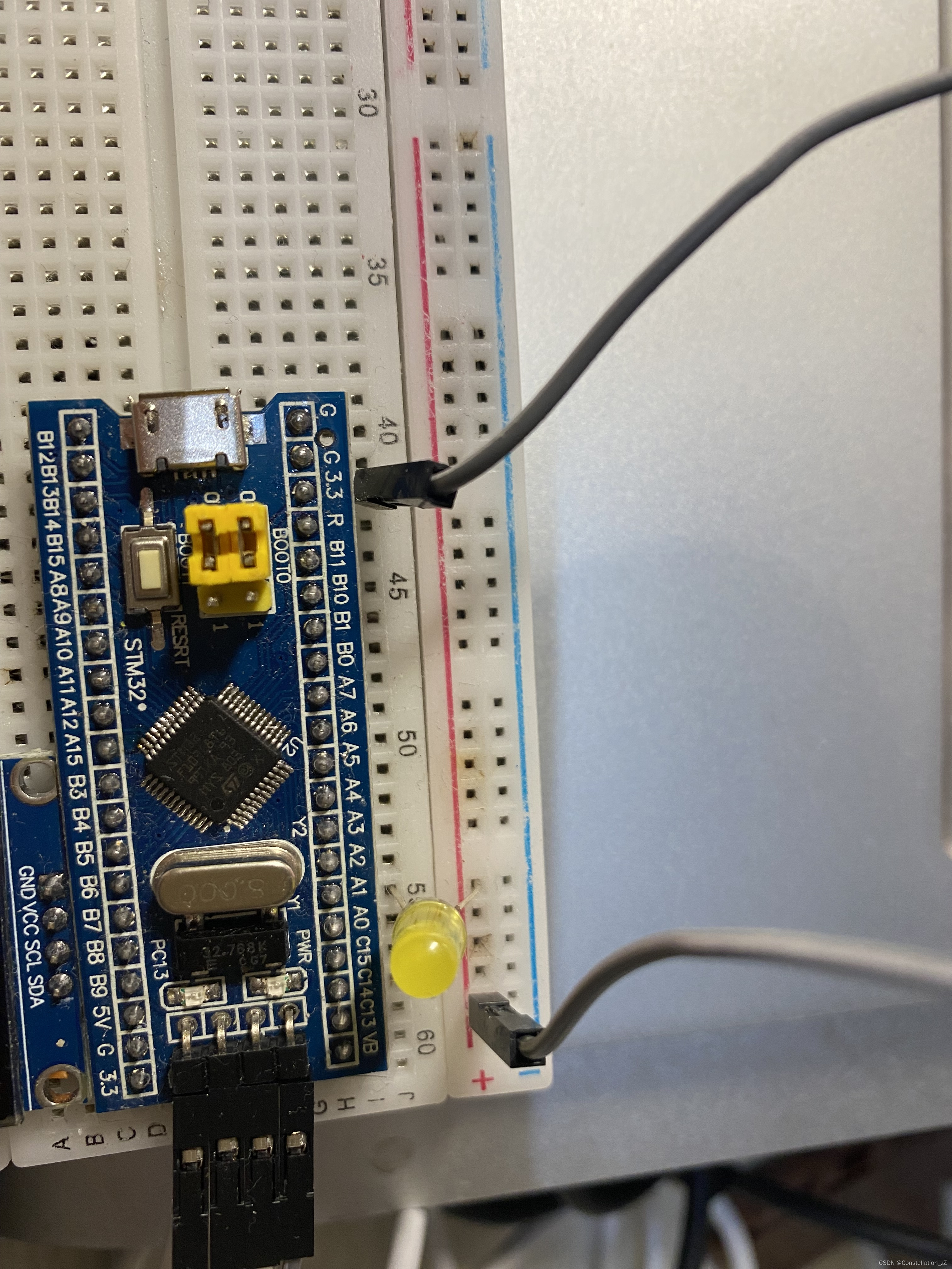
The burning results are as follows:

Turn on the magic wand and set it as follows:


Open keil’s debugging interface and click Logic Analyzer

Click “SET UP” on the interface

Set the following in the pop-up interface (fill in “PORTA.0” in the upper column).

Click “close”, then click on the left to run the program at full speed

The result is as follows:
8. Summary
Through this experiment, I have a deeper understanding of the scheduled interrupt function of STM32, understood the operating principles of different basic scheduled interrupt modes, and also explored the output comparison function of the general timer. By carefully designing parameters such as frequency, duty cycle, and resolution, I successfully simulated an analog-like signal, and used the multiplexing output function of the PA0 pin to output the signal to the port, and finally achieved the display effect of an LED breathing light. .
Although working with the standard library may seem cumbersome, the logical steps are clear. This experiment not only improved my programming skills, but also enhanced my ability to check and avoid errors. I gained a deeper understanding of how to control hardware through programming and how to fine-tune parameters to achieve desired effects.
9. Reference
[6-4] PWM driven LED breathing light & PWM driven servo & PWM driven DC motor_bilibili_bilibili