STM32LED light experiment based on register and firmware library
- 1. Register-based stm32 LED running light program
-
- 1.1 Register
- 1.2 Create a keil project
- 1.3 C language to implement running water lamp
- 2. Stm32 LED running light program based on firmware library
-
- 2.1 Introduction to standard peripheral library
- 2.2stm32F10X standard peripheral library download
- 2.3 Add firmware library
1. Register-based stm32 LED running light program
1.1 Register
Registers are components of the central processing unit and are high-speed storage components with limited storage capacity that can be used to temporarily store instructions, data and addresses. Registers are the top of the memory hierarchy and the fastest way for the system to obtain operating data. Registers are usually measured by the number of bits they can hold, such as “8-bit register” or “32-bit register”. Register is usually used to refer to a group of registers that can be directly indexed by the output or input of an instruction. It is also called “architectural register”. According to different functions, registers can be divided into two categories: basic registers and shift registers.
1.2 Create a keil project
1. Open keil, click Project, and select New uVision Project
2. Select the CPU model and choose according to the development board (we choose STM32F103C8 here)

3. Add library files online
When using registers to control STM32, there is no need to add library files online and can be turned off directly.
4.Add files
①Add existing files
Add the startup file (startup_stm32f10x_hd.s) to the newly created project. This file can be copied to the firmware library here startup_stm32f10x_hd.s.
②Create new file
stm32f10x.h
Created manually, used to store register mapping code, temporarily empty.
main.c
Created manually to store the main function, which is temporarily empty.
5. Configure the Magic Wand tab
①Target settings
 The purpose is to be able to use printf
②Output settings

to generate a hex file when compiling
③Listing settings

Let the output file be located in the Listing folder
④Debug settings

⑤Utilities settings

1.3 C language to implement running water lamp
This time, three lights are used to implement it. The light-on state is represented by 1, and the light-off state is represented by 0.
The initial state is 0 0 0
Status one is 1 0 0
State two is 0 1 0
State three is 0 0 1
After the end of state three, it continues to enter state one, and continues to cycle to achieve the effect of running water lights.
code show as below
#define GPIOB_BASE 0x40010C00
#define GPIOC_BASE 0x40011000
#define GPIOA_BASE 0x40010800

#define RCC_APB2ENR (*(unsigned int *)0x40021018)

#define GPIOB_CRH (*(unsigned int *)0x40010C04)
#define GPIOC_CRH (*(unsigned int *)0x40011004)
#define GPIOA_CRL (*(unsigned int *)0x40010800)

#define GPIOB_ODR (*(unsigned int *)0x40010C0C)
#define GPIOC_ODR (*(unsigned int *)0x4001100C)
#define GPIOA_ODR (*(unsigned int *)0x4001080C)
\t


void Delay_ms(volatile unsigned int);
void A_LED_LIGHT(void);
void B_LED_LIGHT(void);
void C_LED_LIGHT(void);
void Delay_ms( volatile unsigned int t)
{<!-- -->
     unsigned int i;
     while(t--)
         for (i=0;i<800;i + + );
}

void A_LED_LIGHT(){<!-- -->
GPIOA_ODR=0x0<<4; //PA4 low level
GPIOB_ODR=0x1<<9; //PB9 high level
GPIOC_ODR=0x1<<13; //PC13 high level
}
void B_LED_LIGHT(){<!-- -->
GPIOA_ODR=0x1<<4; //PA4 high level
GPIOB_ODR=0x0<<9; //PB9 low level
GPIOC_ODR=0x1<<13; //PC13 high level
}
void C_LED_LIGHT(){<!-- -->
GPIOA_ODR=0x1<<4; //PA4 high level
GPIOB_ODR=0x1<<9; //PB9 high level
GPIOC_ODR=0x0<<13; //PC13 low level
}

int main(){<!-- -->
int j=100;
// Start the clock
RCC_APB2ENR |= (1<<3); // Turn on GPIOB clock
RCC_APB2ENR |= (1<<4); // Turn on GPIOC clock
RCC_APB2ENR |= (1<<2); // Turn on GPIOA clock
\t
\t
//Set GPIO as push-pull output
GPIOB_CRH & amp;= 0xffffff0f; //Set bit clear
GPIOB_CRH|=0x00000020; //PB9 push-pull output

GPIOC_CRH & amp;= ~(1111<<(4*5)); //Set bit and clear
GPIOC_CRH|=(1<<(4*5)); //PC13 push-pull output


GPIOA_CRL & amp;= 0xfff0ffff; //Set bit clear
GPIOA_CRL|=0x00010000; //PA4 push-pull output

// 3 LEDs are initialized to not light up (i.e. high point)
GPIOB_ODR |= (1<<9);
GPIOC_ODR |= (1<<13);
GPIOA_ODR |= (1<<4);
\t
while(j){<!-- -->
\t\t
B_LED_LIGHT();
Delay_ms(10000);

C_LED_LIGHT();
Delay_ms(10000);

A_LED_LIGHT();
Delay_ms(10000);
}
\t
}
In the above code, we call GPIOA_Pin_4, GPIOB_Pin_9 and the pc13 port on the system board through registers, and complete the operation of the running water lamp by setting their high and low level inputs.
2. Stm32 LED running light program based on firmware library
2.1 Introduction to the Standard Peripheral Library
The STM32 standard peripheral library is a firmware function package, which consists of programs, data structures and macros, and includes the performance characteristics of all peripherals of the microcontroller. The function library also includes driver descriptions and application examples for each peripheral, providing an intermediate API for developers to access the underlying hardware. By using the firmware function library, developers can easily apply each peripheral without having to deeply understand the details of the underlying hardware. set up.
2.2stm32F10X standard peripheral library download
We do not need any other special environment configuration to use register lighting, but using the standard peripheral library requires us to go to the stm32 official website to download the firmware library we need.
First we go to the official website
www.st.com


Because the chip type we use is stm32F103C8T6, so here we choose F1

After filling in the valid email address, st official will send us the above email, click DOWNLOAD to download
2.3 Add firmware library
1. Firmware library file classification

Libraries: The folder contains the source code and startup files of the driver library. This is very important. The firmware library we want to use is in this folder.
Project: Under the folder are examples and project templates written using the driver library. The routines written for each peripheral are very useful to us. We can refer to the routines here when learning.
stm32f10x_stdperiph_lib_um.chm: Library help document, this is very useful. If you don’t like to look at the source code directly, you can reasonably query the function description of each peripheral. It is very detailed. This is a compiled HTML file. It mainly describes how to use the driver library. Write your own application
2. Add firmware library
Unzip the file package we downloaded

Copy libraries to our project folder

Open keil software and add libraries files to the project
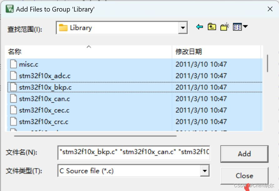
Then we open the magic wand and add the libraries file path
 Click Add. After the addition is completed, we can use the standard peripherals of stm32F103X Firmware library
After configuring our standard library above, we can use the standard library to perform lighting operations. The code is as follows
#include "stm32f10x.h" // Device header
#include "Delay.h"

int main(void)
{<!-- -->
RCC_APB2PeriphClockCmd(RCC_APB2Periph_GPIOA, ENABLE);
\t
GPIO_InitTypeDef GPIO_InitStructure;//Create structure
GPIO_InitStructure.GPIO_Mode = GPIO_Mode_Out_PP;//Set to push-pull output
GPIO_InitStructure.GPIO_Pin = GPIO_Pin_All;//Initialize all pins of GPIOA
GPIO_InitStructure.GPIO_Speed = GPIO_Speed_10MHz;
GPIO_Init(GPIOA, & amp;GPIO_InitStructure);
//Set the serial port to high level. Because the wiring method causes the LED light to light up at low level by default, so turn off the LED light first.
GPIO_SetBits(GPIOA,GPIO_Pin_0);
GPIO_SetBits(GPIOA,GPIO_Pin_1);
GPIO_SetBits(GPIOA,GPIO_Pin_2);
GPIO_SetBits(GPIOA,GPIO_Pin_3);
GPIO_SetBits(GPIOA,GPIO_Pin_4);
GPIO_SetBits(GPIOA,GPIO_Pin_5);
GPIO_SetBits(GPIOA,GPIO_Pin_6);
GPIO_SetBits(GPIOA,GPIO_Pin_7);
\t
while (1)
{<!-- -->
GPIO_ResetBits(GPIOA,GPIO_Pin_0);//Low level lights up
Delay_ms(1000); //Delay 1s
GPIO_SetBits(GPIOA,GPIO_Pin_0); //High level off
GPIO_ResetBits(GPIOA,GPIO_Pin_1);
Delay_ms(1000);
GPIO_SetBits(GPIOA,GPIO_Pin_1);
GPIO_ResetBits(GPIOA,GPIO_Pin_2);
Delay_ms(1000);
GPIO_SetBits(GPIOA,GPIO_Pin_2);
\t\t
GPIO_ResetBits(GPIOA,GPIO_Pin_3);
Delay_ms(1000);
GPIO_SetBits(GPIOA,GPIO_Pin_3);
GPIO_ResetBits(GPIOA,GPIO_Pin_4);
Delay_ms(1000);
GPIO_SetBits(GPIOA,GPIO_Pin_4);
GPIO_ResetBits(GPIOA,GPIO_Pin_5);
Delay_ms(1000);
GPIO_SetBits(GPIOA,GPIO_Pin_5);
GPIO_ResetBits(GPIOA,GPIO_Pin_6);
Delay_ms(1000);
GPIO_SetBits(GPIOA,GPIO_Pin_6);
GPIO_ResetBits(GPIOA,GPIO_Pin_7);
Delay_ms(1000);
GPIO_SetBits(GPIOA,GPIO_Pin_7);;
}
}
In the above code, we use the firmware library to perform the lighting operation. First, we turn on the GPIO clock peripheral, then create a structure, set the parameters inside the structure to set the pin output mode of our GPIO, and then use the standard peripheral library GPIO_ResetBits() and GPIO_SetBits() two library functions to set the high and low levels of the serial port of the peripheral GPIOA. By setting the high and low levels of the serial port through the delay function and intermittently, we can realize the operation of lighting the running water lamp.
