I signed up for the off-road cycling group of the 18th National College Student Smart Car Competition before, but failed to finish the race due to various reasons. So I plan to send out a part of what I have done, hoping to be helpful to the students who have just participated in the competition in the future, and it is also a summary of my life in the past more than one semester. Due to my ignorance and lack of knowledge, if there are inaccuracies or mistakes, please feel free to enlighten me.
The code is based on the CH32V307 open source library of Zhufei Technology.
Why first-order complementary filtering is needed
When we perform attitude calculation through MPU6050, MPU6050 gives us two sets of data: one set comes from the accelerometer and the other set comes from the gyroscope. The data of the two sensors can independently obtain the angle of the car at this time, but they also have their own problems: the accelerometer is relatively sensitive, and the instantaneous error caused by vibration is relatively large; although the angle obtained by the gyroscope integration is relatively small affected by vibration, But with the increase of time, the integral error and temperature drift will gradually increase. To explain it from another perspective, the accelerometer is mainly affected by high-frequency noise, while the gyroscope is mainly affected by low-frequency noise. These two sensors can just make up for each other’s shortcomings. It is more accurate to use a gyroscope for a short time, and it is more accurate to use an accelerometer for a long time; it is more accurate to use a gyroscope when it is in motion, and it is more accurate to use an accelerometer when it is stationary, that is, it is complementary. Through first-order complementary filtering, we filter out the high-frequency part of the accelerometer, filter out the low-frequency part of the gyroscope, and add these two data with a certain weight to get a more accurate angle.
You can see second-order complementary filtering and Kalman filtering in other resources. Compared with these two algorithms, the advantage of the first-order complementary filter is that it has less calculation, faster convergence speed, and is more friendly to chips with weak performance. Although not as accurate as second-order complementary filtering and Kalman filtering, it is still within acceptable limits for our purposes.
Below we combine the code to illustrate the process of attitude calculation based on first-order complementary filtering.
Custom structure
In order to make the code look more elegant, we first define such a structure and declare the corresponding variables to store the data we need.
typedef struct{
    float Roll;//The calculated angle
    float Pitch;
    float Yaw;

    float Roll_a;//The angle calculated by the accelerometer
    float Pitch_a;
    float Roll_g;//The angular velocity calculated by the gyroscope
    float Pitch_g;

    float lastRoll;//The last calculation angle
    float lastPitch;

    int offset_gx;//Gyroscope zero drift value
    int offset_gy;
    int offset_gz;
}IMU;

...

IMU IMU_Data;
Separate calculation of accelerometer and gyroscope
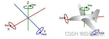
Here we take the Roll angle (rolling angle) of the car, that is, the angle at which the bicycle needs to maintain balance, as an example to explain how to calculate the angle through the accelerometer and gyroscope respectively. An extra note is that the X-axis of this article points to the front of the car, as shown in the figure below, but other information is not necessarily so, please pay more attention when consulting other information.
Accelerometer
IMU_Data.Roll_a=atan2(mpu6050_acc_x,mpu6050_acc_z)/(PI/180);
Friends who are interested in the mathematical derivation process can refer to this blog, and will not explain it here. In short, mpu6050_acc_x and mpu6050_acc_z are the direct data we read through the mpu6050_get_acc function provided by Zhufei library. Through the above mathematical operations, we get the Roll angle Roll_a calculated according to the acceleration, and the unit is degree. The atan2 function is defined in the math.h standard library, which must be included before use.
If you want to calculate the Pitch angle (pitch angle), just change x to y. Unfortunately, due to theoretical limitations, we cannot use acceleration to calculate the Yaw angle (heading angle).
Gyroscope
IMU_Data.Roll_g=-(mpu6050_gyro_y)/14.3;
Through this operation, we can convert the gyroscope data provided by the MPU6050 into actual physical data, and the unit is degrees per second, that is, angular velocity. We only need to integrate the angular velocity to get the angle. We put this processing in the function of the first-order complementary filter. Whether to add a negative sign to the code depends on your sensor chip. The number 14.3 is obtained from the range of the gyroscope. If you use the mpu6050_gyro_transition function of the fly-by-fly library to convert, you don’t need to care about this number.
Similarly, if you want to calculate the Pitch angle, you only need to change y to x. You can even use the Z-axis data to calculate the Yaw angle, but, as we mentioned above, the error will increase over time. To compensate for this error, you can combine GNSS (Global Navigation Satellite System) data, but that’s outside the scope of this article.
First order complementary filtering process
#define Ka 0.80 //acceleration calculation weight
#define dt 0.005 //Sampling interval (unit: second)

float FOCF(float acc_m, float gyro_m, float* last_angle){
    float temp_angle;
    temp_angle=Ka*acc_m + (1-Ka)*(*last_angle + gyro_m*dt);
    *last_angle=temp_angle;
    return temp_angle;
}

...

IMU_Data.Roll=FOCF(IMU_Data.Roll_a,IMU_Data.Roll_g, & amp;IMU_Data.lastRoll);
After processing the data of the accelerometer and gyroscope separately, it is now necessary to complement the two data together. We define a function called FOCF to handle this mathematical process. This function accepts the processed data and the storage address of the last solution result as parameters.
First, we multiply the angular velocity resolved by the gyroscope by the sampling interval to get the angular change since the last sampling. By adding the last calculation result to this change, we can get the new Roll angle calculated by the gyroscope.
Then, we weighted and added the angle obtained by the acceleration solution and the angle obtained by the gyroscope according to the weighting factor, so as to obtain the final solution result. This weight factor needs to be adjusted according to the actual situation.
After the calculation is complete, we update *last_angle for the next calculation. Finally, return the calculated angle as a result, you can read IMU_Data.Roll in other functions, and finally keep your bike in balance.
The same is true for the Pitch angle.
Before solving…
Unfortunately, after you connect the gyroscope, you find that even if you don’t touch it, its data is not 0, which is caused by the inevitable error in the process. Fortunately, this error does not vary much from run to run, allowing us to minimize its impact in a simple way.
Now we define a function IMU_offset to remove zero drift, and call it every time the MCU starts.
#define OFFSET_COUNT 200

void IMU_offset(){
    for(int i=0;i<OFFSET_COUNT;i++){
        system_delay_ms(5);
        if(mpu6050_gyro_x==mpu6050_gyro_y){
            i--;
        }
        else {
            IMU_Data.offset_gx + =mpu6050_gyro_x;
            IMU_Data.offset_gy + =mpu6050_gyro_y;
            IMU_Data.offset_gz + =mpu6050_gyro_z;
        }
    }
    IMU_Data.offset_gx/=OFFSET_COUNT;
    IMU_Data.offset_gy/=OFFSET_COUNT;
    IMU_Data.offset_gz/=OFFSET_COUNT;
}
Since it doesn’t vary much, we just ask for its average and subtract it at each sample. This function plays the role of averaging. OFFSET_COUNT is the amount of data you want to collect, just take an appropriate value. The 5 in system_delay_ms(5) is the sampling interval you specified.
Considering that sometimes the Dupont line may have poor contact in practical applications, a simple judgment is made in the code. When a bad contact occurs, the X-axis data will be the same as the Y-axis data (usually both are 0, but there are occasional accidents), and we consider the data to be invalid. This is a wild way to explore after being troubled by the Dupont line for a long time, and it should be used as a reference.
In summary
When we’ve done all the code above, it’s time to call them. The function to remove zero drift should be called at startup, which is the beginning of the main function. In order to ensure that our sampling interval is constant, we need to execute the function in the interrupt handler of the timer. The code is divided into two parts: in the first part, you need to read the original data from the MPU6050, and subtract the zero drift value you calculated from the original data of the gyroscope; in the second part, you need to process the accelerometer and The data from the gyroscope is then subjected to first-order complementary filtering.
The above is the whole process of attitude calculation based on first-order complementary filtering, and I hope it can be helpful to students.
(I feel that this stuff is badly written in every sense…)