1.Background
The author once used the 6-axis gyroscope module mpu6050 module and found that there was a serious zero drift problem. I also checked many methods on the Internet, such as delay, etc., but they could not solve the problem, so I attributed the problem to the fact that the module only has 6 axes. , so now I have replaced it with a 9-axis gyroscope – jy901s module, and found that there is still zero drift, but it is much better than mpu6050, so I found a HWT101CT gyroscope module, and I will try this plan in the future.
Total: mpu6050 ——– The drift is about 10°;
jy901s ——– The drift is about 2°;
HWT101CT ——– To be tested, but my personal feeling is basically 0.
2. Part of the code
(1)JY901S.c code
#include "stm32f10x.h" // Device header
#include "JY901S.h"
#include "JY901S_Reg.h"

#define JY901S_ADDRESS 0xa0

unsigned char yawAngle[2];
int flag = 0;

void MyDMA_Transfer(int BufferSize_DMA) //In single transfer mode, to reinstall DMA_BufferSize, you need to disable the DMA channel first
{
DMA_Cmd(DMA1_Channel5, DISABLE);
DMA_SetCurrDataCounter(DMA1_Channel5, BufferSize_DMA);
DMA_Cmd(DMA1_Channel5, ENABLE);
\t
while (DMA_GetFlagStatus(DMA1_FLAG_TC5) == RESET);
DMA_ClearFlag(DMA1_FLAG_TC5);
}


void JY901S_WaitEvent(I2C_TypeDef* I2Cx, uint32_t I2C_EVENT)
{
uint32_t Timeout;
Timeout = 10000;
while (I2C_CheckEvent(I2Cx, I2C_EVENT) != SUCCESS)
{
Timeout --;
if (Timeout == 0)
{
break;
}
}
}

void JY901S_WriteReg(uint8_t RegAddress, uint8_t Data)
{
I2C_GenerateSTART(I2C2, ENABLE);
JY901S_WaitEvent(I2C2, I2C_EVENT_MASTER_MODE_SELECT);//EV5
\t
I2C_Send7bitAddress(I2C2, JY901S_ADDRESS, I2C_Direction_Transmitter);
JY901S_WaitEvent(I2C2, I2C_EVENT_MASTER_TRANSMITTER_MODE_SELECTED);//EV6
\t
I2C_SendData(I2C2, RegAddress);
JY901S_WaitEvent(I2C2, I2C_EVENT_MASTER_BYTE_TRANSMITTING);//EV8
\t
I2C_SendData(I2C2, Data);
JY901S_WaitEvent(I2C2, I2C_EVENT_MASTER_BYTE_TRANSMITTED);//EV8_2
\t
I2C_GenerateSTOP(I2C2, ENABLE);
}

void JY901S_ReadReg(uint8_t RegAddress)
{
int8_t length;
\t
I2C_GenerateSTART(I2C2, ENABLE);
JY901S_WaitEvent(I2C2, I2C_EVENT_MASTER_MODE_SELECT);//EV5
\t
I2C_Send7bitAddress(I2C2, JY901S_ADDRESS, I2C_Direction_Transmitter);
JY901S_WaitEvent(I2C2, I2C_EVENT_MASTER_TRANSMITTER_MODE_SELECTED);//EV6
\t
I2C_SendData(I2C2, RegAddress);
JY901S_WaitEvent(I2C2, I2C_EVENT_MASTER_BYTE_TRANSMITTED);//EV8_2
\t
I2C_GenerateSTART(I2C2, ENABLE);
JY901S_WaitEvent(I2C2, I2C_EVENT_MASTER_MODE_SELECT);//EV5
\t
I2C_Send7bitAddress(I2C2, JY901S_ADDRESS, I2C_Direction_Receiver);
JY901S_WaitEvent(I2C2, I2C_EVENT_MASTER_RECEIVER_MODE_SELECTED);//EV6
\t
if(flag != 0)MyDMA_Transfer(2);

for(int8_t count=0;count<length;count + + ){
if(count!=length-1)
{
JY901S_WaitEvent(I2C2, I2C_EVENT_MASTER_BYTE_RECEIVED);//EV_7
}
else{
I2C_AcknowledgeConfig(I2C2, DISABLE);
I2C_GenerateSTOP(I2C2, ENABLE);
JY901S_WaitEvent(I2C2, I2C_EVENT_MASTER_BYTE_RECEIVED);//EV_7
}
}
flag + + ;
\t\t
}

void JY901S_Init(void)
{
RCC_APB1PeriphClockCmd(RCC_APB1Periph_I2C2, ENABLE);
RCC_APB2PeriphClockCmd(RCC_APB2Periph_GPIOB, ENABLE);
RCC_AHBPeriphClockCmd(RCC_AHBPeriph_DMA1, ENABLE);
\t
GPIO_InitTypeDef GPIO_InitStructure;
GPIO_InitStructure.GPIO_Mode = GPIO_Mode_AF_PP;
GPIO_InitStructure.GPIO_Pin = GPIO_Pin_10 | GPIO_Pin_11;
GPIO_InitStructure.GPIO_Speed = GPIO_Speed_50MHz;
GPIO_Init(GPIOB, &GPIO_InitStructure);
\t
I2C_InitTypeDef I2C_InitStructure;
I2C_InitStructure.I2C_Mode = I2C_Mode_I2C;
I2C_InitStructure.I2C_ClockSpeed = 50000;
I2C_InitStructure.I2C_DutyCycle = I2C_DutyCycle_2;
I2C_InitStructure.I2C_Ack = I2C_Ack_Enable;
I2C_InitStructure.I2C_AcknowledgedAddress = I2C_AcknowledgedAddress_7bit;
I2C_InitStructure.I2C_OwnAddress1 = 0x00;
I2C_Init(I2C2, & amp;I2C_InitStructure);
\t
I2C_Cmd(I2C2, ENABLE);
\t
DMA_InitTypeDef DMA_InitStructure;
  DMA_DeInit(DMA1_Channel5);
  DMA_InitStructure.DMA_PeripheralBaseAddr = (uint32_t) & amp;(I2C2->DR);
  DMA_InitStructure.DMA_MemoryBaseAddr = (uint32_t)yawAngle;
  DMA_InitStructure.DMA_DIR = DMA_DIR_PeripheralSRC;
  DMA_InitStructure.DMA_BufferSize = 2; // The yaw angle register is 2 bytes
  DMA_InitStructure.DMA_PeripheralInc = DMA_PeripheralInc_Disable; //Address increases automatically
  DMA_InitStructure.DMA_MemoryInc = DMA_MemoryInc_Enable;
  DMA_InitStructure.DMA_PeripheralDataSize = DMA_PeripheralDataSize_Byte; //DMA_PeripheralDataSize_Byte byte int_8; DMA_PeripheralDataSize_HalfWord int_16; DMA_PeripheralDataSize_Word int_32
  DMA_InitStructure.DMA_MemoryDataSize = DMA_MemoryDataSize_Byte;
  DMA_InitStructure.DMA_Mode = DMA_Mode_Normal; //DMA_Mode_Normal single transfer; DMA_Mode_Circular cyclic transfer;
  DMA_InitStructure.DMA_Priority = DMA_Priority_High;
  DMA_InitStructure.DMA_M2M = DMA_M2M_Disable; //DMA_M2M_Disable hardware trigger; sometimes choose DMA_M2M_Enable software trigger; (register to register) software trigger: complete the transfer at the fastest speed
//Hardware trigger conditions: the count is not 0 (DMA_BufferSize); there is a trigger source; the corresponding channel is enabled.
  DMA_Init(DMA1_Channel5, & DMA_InitStructure);

    // Enable DMA1 channel 5
  DMA_Cmd(DMA1_Channel5, ENABLE);
// Start DMA transfer
I2C_DMACmd(I2C2, ENABLE);
}
(2)JY901S.h code
#ifndef __JY901S_H
#define __JY901S_H

extern unsigned char yawAngle[2];

void MyDMA_Transfer(int BufferSize_DMA);
void JY901S_WaitEvent(I2C_TypeDef* I2Cx, uint32_t I2C_EVENT);
void JY901S_WriteReg(uint8_t RegAddress, uint8_t Data);
void JY901S_ReadReg(uint8_t RegAddress);
void JY901S_Init(void);

#endif
(3)JY901S_REG code
#ifndef __JY901S_REG_H
#define __JY901S_REG_H

#define SAVE 0x00
#define CALSW 0x01
#define RSW 0x02
#defineRRATE 0x03
#define BAUD 0x04
#defineAXOFFSET 0x05
#define AYOFFSET 0x06
#defineAZOFFSET 0x07
#define GXOFFSET 0x08
#define GYOFFSET 0x09
#define GZOFFSET 0x0a
#define HXOFFSET 0x0b
#define HYOFFSET 0x0c
#define HZOFFSET 0x0d
#define D0MODE 0x0e
#define D1MODE 0x0f
#define D2MODE 0x10
#define D3MODE 0x11
#define D0PWMH 0x12
#define D1PWMH 0x13
#define D2PWMH 0x14
#define D3PWMH 0x15
#define D0PWMT 0x16
#define D1PWMT 0x17
#define D2PWMT 0x18
#define D3PWMT 0x19
#define IICADDR 0x1a
#define LEDOFF 0x1b
#define GPSBAUD 0x1c

#define YYMM 0x30
#defineDDHH 0x31
#defineMMSS 0x32
#define MS 0x33
#defineAX 0x34
#defineAY 0x35
#defineAZ 0x36
#define GX 0x37
#define GY 0x38
#define GZ 0x39
#define HX 0x3a
#define HY 0x3b
#define HZ 0x3c
#define Roll 0x3d
#define Pitch 0x3e
#define Yaw 0x3f
#define TEMP 0x40
#define D0Status 0x41
#define D1Status 0x42
#define D2Status 0x43
#define D3Status 0x44
#define PressureL 0x45
#define PressureH 0x46
#defineHeightL 0x47
#defineHeightH 0x48
#define LonL 0x49
#define LonH 0x4a
#defineLatL 0x4b
#defineLatH 0x4c
#define GPSHeight 0x4d
#define GPSYAW 0x4e
#define GPSVL 0x4f
#define GPSVH 0x50

#define DIO_MODE_AIN 0
#define DIO_MODE_DIN 1
#define DIO_MODE_DOH 2
#define DIO_MODE_DOL 3
#define DIO_MODE_DOPWM 4
#define DIO_MODE_GPS 5

#endif
(4)main.c code
#include "stm32f10x.h" // Device header
#include "Delay.h"
#include "OLED.h"
#include "JY901S.h"
#include "JY901S_Reg.h"

float Z_Angle;

int main(void)
{
OLED_Init();
JY901S_Init();
\t\t
while (1)
{
JY901S_ReadReg(Yaw);
Z_Angle = ((yawAngle[1] << 8) | yawAngle[0])*180/32768;
\t\t
OLED_ShowHexNum(3, 3, yawAngle[1], 2);
OLED_ShowHexNum(3, 5, yawAngle[0], 2);
\t\t
OLED_ShowSignedNum(2, 8, Z_Angle, 6);
Delay_ms(1000);
}
}
3. Code analysis
(1) Configuration code analysis
First, we need to configure and initialize our peripheral resources.

Turning on the clock, configuring the GPIO port, peripherals, and enabling them are all routine operations, so I won’t go into details.

Then turn on the DMA clock and explain that stm32f103c8t6 only has DMA1 and no DMA2!
Then configure DMA1_Channel5. Note that each peripheral will only correspond to a unique DMA channel! Refer to the picture below.

What I am using here is I2C2_RX, so channel 5 is requested, which is DMA1_Channel5.
I have comments on other configurations and will not communicate in the comment area!
(2) I2C and DMA working logic code analysis

This is a function that reads the corresponding register package, and its parameter is the address of the read register.
Compare the I2C communication protocol diagram:


It can be concluded that the logic of reading the corresponding register of the slave is
1. I2C_GenerateSTART(I2C2, ENABLE);
JY901S_WaitEvent(I2C2, I2C_EVENT_MASTER_MODE_SELECT);//EV5
Generates the I2C start condition and waits for the EV5 event.
(Explain why there is a waiting event: read the value of the slave register and flush it back to the shift register of stm32, and then move it into the data register to wait for transfer. The event is just a sign of the status of the shift register, marking whether the previous one has been shifted out of the shift register. Bytes of data, I want to move in the next byte of data, the same is true for data registers)
2. I2C_Send7bitAddress(I2C2, JY901S_ADDRESS, I2C_Direction_Transmitter);
JY901S_WaitEvent(I2C2, I2C_EVENT_MASTER_TRANSMITTER_MODE_SELECTED);//EV6
Send to the slave (slave address shifted one bit to the left), confirm that the object is correct, and wait for the EV6 event.
I2C_Direction_Transmitter is written.
Because a 7-bit address is used, and a byte is 8 bits, the slave address can be shifted left by one bit, and the eighth bit is used as the determining read and write bit. This design idea is really strong! ! ! , so I assigned the macro address to 0xa0 instead of 0x50.

0x50 0101 0000 0xa0 1010 0000
That is 0xa0 = (0x50 << 1)
3. I2C_SendData(I2C2, RegAddress);
JY901S_WaitEvent(I2C2, I2C_EVENT_MASTER_BYTE_TRANSMITTED);//EV8_2
Write the address of the read register to the slave and wait for the “write end” event EV8_2.
Why? What is the use?
Function: Point the pointer of the slave data register to the corresponding register. The data read in step 6 will be the value pointed to by this pointer.
4. I2C_GenerateSTART(I2C2, ENABLE);
JY901S_WaitEvent(I2C2, I2C_EVENT_MASTER_MODE_SELECT);//EV5
Generates a restart I2C start condition and waits for the EV5 event.
5. I2C_Send7bitAddress(I2C2, JY901S_ADDRESS, I2C_Direction_Receiver);
JY901S_WaitEvent(I2C2, I2C_EVENT_MASTER_RECEIVER_MODE_SELECTED);//EV6
Send a read command to the slave and wait for the EV6 event.
6.
void MyDMA_Transfer(int BufferSize_DMA) //In single transfer mode, to reinstall DMA_BufferSize, you need to disable the DMA channel first
{
DMA_Cmd(DMA1_Channel5, DISABLE);
DMA_SetCurrDataCounter(DMA1_Channel5, BufferSize_DMA);
DMA_Cmd(DMA1_Channel5, ENABLE);
\t
while (DMA_GetFlagStatus(DMA1_FLAG_TC5) == RESET);
DMA_ClearFlag(DMA1_FLAG_TC5);
}
The void MyDMA_Transfer(int BufferSize_DMA) function encapsulates reloading (DMA transfer times DMA_BufferSize).

That is, DMA_InitStructure.DMA_BufferSize = 2; // The yaw angle register in the above picture is 2 bytes
Because I only read the yaw angle, the corresponding register is Yaw, and

There are two bytes under each address, so I need to DMA transfer it twice, corresponding to DMA_PeripheralDataSize_Byte byte int_8, and transfer 8 bits at a time, that is, one byte, as configured in the previous initialization function.
if(flag != 0)MyDMA_Transfer(2);

for(int8_t count=0;count<length;count + + ){
if(count!=length-1)
{
JY901S_WaitEvent(I2C2, I2C_EVENT_MASTER_BYTE_RECEIVED);//EV_7
}
else{
I2C_AcknowledgeConfig(I2C2, DISABLE);
I2C_GenerateSTOP(I2C2, ENABLE);
JY901S_WaitEvent(I2C2, I2C_EVENT_MASTER_BYTE_RECEIVED);//EV_7
}
}
flag + + ;
The idea is that after turning on DMA transfer, it is in single-shot mode, so it stops after transferring 2 bytes, and we need to continue to read data, so we need to reload and transfer the number of times. The flag is used to record how many times it has been reloaded. The initial The value is 0. Use if to determine whether there are 2 transfer times at the beginning of the program, that is, the first set of data does not need to be reloaded at the beginning, flag + +. For loop, I pass in 2 for length, because there are only two bytes, and the first byte is waiting for the EV7 event, the data will be flushed into the data register, and the DMA will move it away, and the second byte is also the last word. section, the I2C protocol stipulates that non-response and stop conditions should be given before waiting for the “read end” event, so first
I2C_AcknowledgeConfig(I2C2, DISABLE);
I2C_GenerateSTOP(I2C2, ENABLE);
back
JY901S_WaitEvent(I2C2, I2C_EVENT_MASTER_BYTE_RECEIVED);//EV_7
7. Just read the value of the target register for DMA transfer in main.c.

JY901S_ReadReg(Yaw);
Z_Angle = ((yawAngle[1] << 8) | yawAngle[0])*180/32768;
Because
Therefore, the high bit read out is shifted eight bits to the left to form an int16 data.
4. Effect demonstration
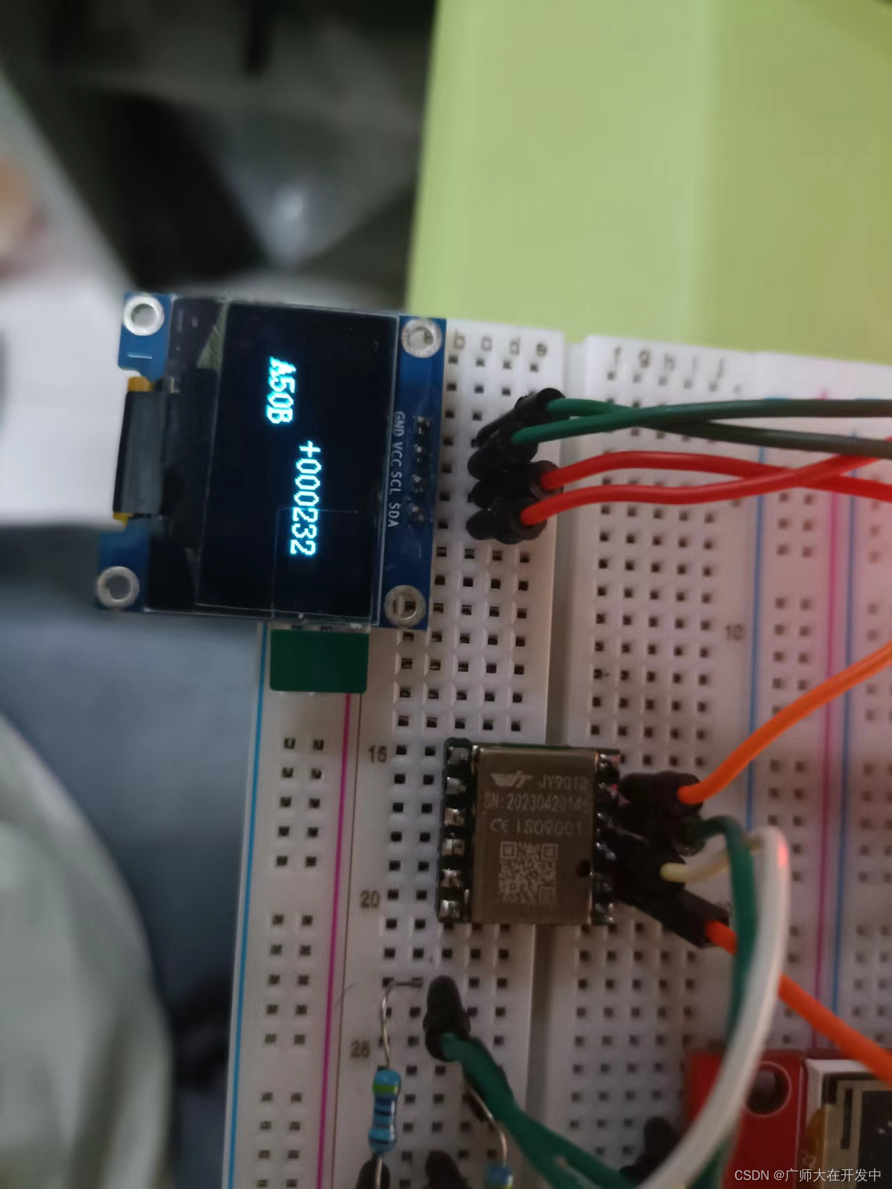
The 16-bit data read is 0xA50B, converted to decimal and brought into the formula ((yawAngle[1] << 8) | yawAngle[0])*180/32768;
calculated

Matches + 232, indicating that the data is read correctly.
Thanks for watching!