Analog pins are used to measure sensor values. It can record a wide range of values compared to digital pins that only provide on/off status. Following the traditional approach, each analog input pin measured by the microcontroller allows only one sensor to be connected and measured. If you need to measure the values of two sensors (e.g. temperature and sunlight intensity), you need to occupy 2 analog input pins on the microcontroller.
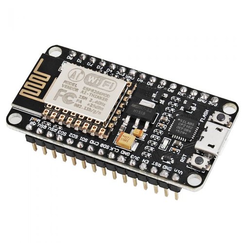
NodeMCU is a very famous microcontroller board with built-in WiFi module. Not only is it an affordable microcontroller, it can do a lot, especially for Internet of Things (IoT) applications. Two of the most common IoT applications are smart home automation, such as controlling loads via remote execution and monitoring buttons. IoT is also known for displaying real-time sensor values online while recording the data as historical values on a web server, which we can access at any time.
However, the biggest drawback of theNodeMCU board is that it only has one analog pin. In other words, it can only take measurements from 1 sensor. If our project requires multiple sensors, we will need to find another microcontroller with more analog pins, such as an Arduino UNO or MEGA. But these motherboards typically do not include built-in WiFi modules and may require additional wiring and WiFi modules.

Today we are going to use another approach, which is to use an expansion board called an analog multiplexer module. It is a microchip that requires 2 to 4 digital pins and 1 analog pin to convert up to 16 analog pins. It may sound complicated at first, but once we know how it works, it’s easy to apply.
NodeMCU Microcontroller
NodeMCU microcontroller is similar to Arduino microcontroller board. It is compatible with Arduino IDE software, has a built-in ESP8266 module and can be connected to the Internet.

Node MCU Microcontroller Base
Node-based MCUs can provide greater flexibility in connection ports to support more sensors. Additionally, it has a 12V input port.

16-channel analog multiplexer moduleCD74HC4067
This module is an expansion board that allows the microcontroller to have more analog pins for sensor measurements. This is very important for NodeMCU since it only has one analog pin.
Multiplexer module concept
A multiplexer module is a microchip that requires1 analog pin and 2 to 4 digital pinsto allow the microcontroller to monitor more analog pins for sensor readings. The 1 analog pin requirement is actually an output pin shared by all extended analog pins. The module only allows 1 analog channel or sensor value to be connected to the output analog pin at a time, so they take turns.
In order to determine which analog channel to open, a microcontroller such as the NodeMCUneeds to send a binary command(a combination of on/off or high/low) to the module via a digital pin in order to allow selection of the channel to be activated on specific time. Binary commands are operated by high/low voltage, and each analog channel has its own unique binary combination. For example, here is a 16-channel analog multiplexer and its binary commands:

For example, if we want to measure channel C15, we can program the 4 digital pin high (5V) outputs to the multiplexer. In effect, we program the NodeMCU to rotate the output commands while measuring each channel output using the same analog input A0. The whole process happens very quickly and we can get readings from the module for all 16 channels.

Hardware wiring

Wiring summary
1 – SIG analog pin connected to A0 of NodeMC
2 – NodeMCU’s digital pin D0 is connected to S0
3 – NodeMCU’s digital pin D1 is connected to S1
4 – NodeMCU’s digital pin D2 is connected to S2
5 – NodeMCU’s digital pin D3 is connected to S3
6 – NodeMCU’s ground is connected to EN
7 – NodeMCU’s Gnd power pin is grounded
8 – VCC power pin connected to 5V on NodeMCU base
9 – C0 to C15 will be analog input pins and are user definable.
Software Code
Before uploading the code to NodeMCU, if this is your first time using NodeMCU, you need to add ESP8266 support files and add the NodeMCU board library Added to IDE software. To add ESP8266 support files, open the Arduino IDE software, go tofiles>preferences>Additional Boards Manager URLs, link this tohttp://arduino.esp8266.com/stable/package_esp8266com_index. json Paste into the black space and click OK.

After completing this step, go to Tools > Boards > Board Manager and download the ESP8266 library through the ESP8266 Community


Once completed, you can start downloading the .ino code file below and uploading it to the NodeMCU board.
 /* 0- General */

    #define S0 D0 /* Assign Multiplexer pin S0 connect to pin D0 of NodeMCU */
    #define S1 D1 /* Assign Multiplexer pin S1 connect to pin D1 of NodeMCU */
    #define S2 D2 /* Assign Multiplexer pin S2 connect to pin D2 of NodeMCU */
    #define S3 D3 /* Assign Multiplexer pin S3 connect to pin D3 of NodeMCU */
    #define SIG A0 /* Assign SIG pin as Analog output for all 16 channels of Multiplexer to pin A0 of NodeMCU */

    int decimal = 2; // Decimal places of the sensor value outputs
    int sensor0; /* Assign the name "sensor0" as analog output value from Channel C0 */
    int sensor1; /* Assign the name "sensor1" as analog output value from Channel C1 */
    int sensor2; /* Assign the name "sensor2" as analog output value from Channel C2 */
    int sensor3; /* Assign the name "sensor3" as analog output value from Channel C3 */
    int sensor4; /* Assign the name "sensor4" as analog output value from Channel C4 */
    int sensor5; /* Assign the name "sensor5" as analog output value from Channel C5 */
    int sensor6; /* Assign the name "sensor6" as analog output value from Channel C6 */
    int sensor7; /* Assign the name "sensor7" as analog output value from Channel C7 */
    int sensor8; /* Assign the name "sensor8" as analog output value from Channel C8 */
    int sensor9; /* Assign the name "sensor9" as analog output value from Channel C9 */
    int sensor10; /* Assign the name "sensor10" as analog output value from Channel C10 */
    int sensor11; /* Assign the name "sensor11" as analog output value from Channel C11 */
    int sensor12; /* Assign the name "sensor12" as analog output value from Channel C12 */
    int sensor13; /* Assign the name "sensor13" as analog output value from Channel C13 */
    int sensor14; /* Assign the name "sensor14" as analog output value from Channel C14 */
    int sensor15; /* Assign the name "sensor15" as analog output value from Channel C15 */


void setup() { /* Put your codes here to run only once during micro controller startup */

    /* 0- General */

    pinMode(S0,OUTPUT); /* Define digital signal pin as output to the Multiplexer pin SO */
    pinMode(S1,OUTPUT); /* Define digital signal pin as output to the Multiplexer pin S1 */
    pinMode(S2,OUTPUT); /* Define digital signal pin as output to the Multiplexer pin S2 */
    pinMode(S3,OUTPUT); /* Define digital signal pin as output to the Multiplexer pin S3 */
    pinMode(SIG, INPUT); /* Define analog signal pin as input or receiver from the Multiplexer pin SIG */

    Serial.begin(9600); /* to display readings in Serial Monitor at 9600 baud rates */

}

void loop() { /* Put your codes here to run over and over again endlessly */

    /* 0- General */

    // Channel 0 (C0 pin - binary output 0,0,0,0)
    digitalWrite(S0,LOW);
    digitalWrite(S1,LOW);
    digitalWrite(S2,LOW);
    digitalWrite(S3,LOW);
    sensor0 = analogRead(SIG);

    // Channel 1 (C1 pin - binary output 1,0,0,0)
    digitalWrite(S0,HIGH);
    digitalWrite(S1,LOW);
    digitalWrite(S2,LOW);
    digitalWrite(S3,LOW);
    sensor1 = analogRead(SIG);

    // Channel 2 (C2 pin - binary output 0,1,0,0)
    digitalWrite(S0,LOW);
    digitalWrite(S1,HIGH);
    digitalWrite(S2,LOW);
    digitalWrite(S3,LOW);
    sensor2 = analogRead(SIG);

    // Channel 3 (C3 pin - binary output 1,1,0,0)
    digitalWrite(S0,HIGH);
    digitalWrite(S1,HIGH);
    digitalWrite(S2,LOW);
    digitalWrite(S3,LOW);
    sensor3 = analogRead(SIG);

    // Channel 4 (C4 pin - binary output 0,0,1,0)
    digitalWrite(S0,LOW); digitalWrite(S1,LOW); digitalWrite(S2,HIGH); digitalWrite(S3,LOW);
    sensor4 = analogRead(SIG);

    // Channel 5 (C5 pin - binary output 1,0,1,0)
    digitalWrite(S0,HIGH); digitalWrite(S1,LOW); digitalWrite(S2,HIGH); digitalWrite(S3,LOW);
    sensor5 = analogRead(SIG);

    // Channel 6 (C6 pin - binary output 0,1,1,0)
    digitalWrite(S0,LOW); digitalWrite(S1,HIGH); digitalWrite(S2,HIGH); digitalWrite(S3,LOW);
    sensor6 = analogRead(SIG);

    // Channel 7 (C7 pin - binary output 1,1,1,0)
    digitalWrite(S0,HIGH); digitalWrite(S1,HIGH); digitalWrite(S2,HIGH); digitalWrite(S3,LOW);
    sensor7 = analogRead(SIG);

    // Channel 8 (C8 pin - binary output 0,0,0,1)
    digitalWrite(S0,LOW); digitalWrite(S1,LOW); digitalWrite(S2,LOW); digitalWrite(S3,HIGH);
    sensor8 = analogRead(SIG);

    // Channel 9 (C9 pin - binary output 1,0,0,1)
    digitalWrite(S0,HIGH); digitalWrite(S1,LOW); digitalWrite(S2,LOW); digitalWrite(S3,HIGH);
    sensor9 = analogRead(SIG);

    // Channel 10 (C10 pin - binary output 0,1,0,1)
    digitalWrite(S0,LOW); digitalWrite(S1,HIGH); digitalWrite(S2,LOW); digitalWrite(S3,HIGH);
    sensor10 = analogRead(SIG);

    // Channel 11 (C11 pin - binary output 1,1,0,1)
    digitalWrite(S0,HIGH); digitalWrite(S1,HIGH); digitalWrite(S2,LOW); digitalWrite(S3,HIGH);
    sensor11 = analogRead(SIG);

    // Channel 12 (C12 pin - binary output 0,0,1,1)
    digitalWrite(S0,LOW); digitalWrite(S1,LOW); digitalWrite(S2,HIGH); digitalWrite(S3,HIGH);
    sensor12 = analogRead(SIG);

    // Channel 13 (C13 pin - binary output 1,0,1,1)
    digitalWrite(S0,HIGH); digitalWrite(S1,LOW); digitalWrite(S2,HIGH); digitalWrite(S3,HIGH);
    sensor13 = analogRead(SIG);

    // Channel 14 (C14 pin - binary output 0,1,1,1)
    digitalWrite(S0,LOW); digitalWrite(S1,HIGH); digitalWrite(S2,HIGH); digitalWrite(S3,HIGH);
    sensor14 = analogRead(SIG);

    // Channel 15 (C15 pin - binary output 1,1,1,1)
    digitalWrite(S0,HIGH); digitalWrite(S1,HIGH); digitalWrite(S2,HIGH); digitalWrite(S3,HIGH);
    sensor15 = analogRead(SIG);

    Serial.print("Sensor 0 : ");Serial.println(sensor0); /* state value for sensor 0 */
    Serial.print("Sensor 1 : ");Serial.println(sensor1); /* state value for sensor 1 */
    Serial.print("Sensor 2 : ");Serial.println(sensor2); /* state value for sensor 2 */
    Serial.print("Sensor 3 : ");Serial.println(sensor3); /* state value for sensor 3 */
    Serial.print("Sensor 4 : ");Serial.println(sensor4); /* state value for sensor 4 */
    Serial.print("Sensor 5 : ");Serial.println(sensor5); /* state value for sensor 5 */
    Serial.print("Sensor 6 : ");Serial.println(sensor6); /* state value for sensor 6 */
    Serial.print("Sensor 7 : ");Serial.println(sensor7); /* state value for sensor 7 */
    Serial.print("Sensor 8 : ");Serial.println(sensor8); /* state value for sensor 8 */
    Serial.print("Sensor 9 : ");Serial.println(sensor9); /* state value for sensor 9 */
    Serial.print("Sensor 10 : ");Serial.println(sensor10); /* state value for sensor 10 */
    Serial.print("Sensor 11 : ");Serial.println(sensor11); /* state value for sensor 11 */
    Serial.print("Sensor 12 : ");Serial.println(sensor12); /* state value for sensor 12 */
    Serial.print("Sensor 13 : ");Serial.println(sensor13); /* state value for sensor 13 */
    Serial.print("Sensor 14 : ");Serial.println(sensor14); /* state value for sensor 14 */
    Serial.print("Sensor 15 : ");Serial.println(sensor15); /* state value for sensor 15 */

    delay(1000); // Read the value every second

}
The above procedures and wiring methods are suitable for situations where you really need 16 sensors. What should you do if you don’t need to connect so many sensors? If you need to connect less than 8 sensors, just connect S3 to GND. If you need to connect 4 For sensors within 1, connect S2 and S3 to GND.
Simplified procedures:
int PING[]={16, 5, 4, 0};

int DATA[16][4] = {
  {0, 0, 0, 0},
  {1, 0, 0, 0},
  {0, 1, 0, 0},
  {1, 1, 0, 0},
  {0, 0, 1, 0},
  {1, 0, 1, 0},
  {0, 1, 1, 0},
  {1, 1, 1, 0},
  {0, 0, 0, 1},
  {1, 0, 0, 1},
  {0, 1, 0, 1},
  {1, 1, 0, 1},
  {1, 0, 1, 1},
  {0, 1, 1, 1},
  {1, 0, 1, 1},
  {1, 1, 1, 1}
};

void setup(){
  pinMode(A0, INPUT);
  Serial.begin(9600);
}

void loop(){
  for (int j = 0; j <= 15; j = j + (1)) {
    for (int i = 0; i <= 3; i = i + (1)) {
      pinMode(PING[i], OUTPUT);
      digitalWrite(PING[i],DATA[j][i]);
      Serial.println(String("S") + String(i) + String("=") + String(analogRead(A0)));
    }
  }
Program in mixly:
 < strong>Use the output function of the chip to realize the running water lamp: use CD74HC4067 to make 16 running water lamps
 < strong>Use the output function of the chip to realize the running water lamp: use CD74HC4067 to make 16 running water lamps
The knowledge points of the article match the official knowledge files, and you can further learn relevant knowledge. Python entry skill treeHomepageOverview 339640 people are learning the system