[STM32] Implement running water lamp and interrupt control based on HAL library
- 1. Configure the project through STMCube and implement LED running lights
-
- 1. Project configuration
- 2. Realization of LED running lights
- 2. Interrupt control to realize LED running lights
-
- 1. What is an interrupt and what is its function?
- 2. Project creation
- 3. Code implementation
- 4. Line connection and effect demonstration
- 3. Experimental experience
Preface
The devices and software used in this experiment are as follows:
Software version:
STM32CubeMX:6.35, KEIl:5.31, FlyMcu or mcuisp (burn-in software)
Hardware:
STM32F103C8T core board, breadboard, usb to ttl, some DuPont wires, three LED lights
1. Configure the project through STMCube and implement LED running lights
1. Project configuration
1. Start the creation of the project based on the chip 
2. Pay attention to entering the chip model

3. Configure debugging interface

4. Configure the clock mode, as follows:

Disable internal clock
BYPASS: Bypass clock
Crystal: crystal/ceramic oscillator
4. Configure GPIO
Here we need three output ports. To be simple, just choose PA0, PA1, PA2, three pins.
Click on the pin you want to use, and then set it. Note that all three must be set.


The above two pictures are from the data. We can ignore them in this experiment.
5. Clock configuration,
The specific configuration is as shown below

6. Project configuration
Click Project manager
Name the project name yourself without spaces. Select the path. It is best to create a new folder yourself.


At this point we have successfully created a project
2. Implementation of LED running lights
1. First, let’s go back to keil
Find the main.c file

Write the following code in the while loop of the main function

 HAL_GPIO_WritePin(GPIOA,GPIO_PIN_0,GPIO_PIN_RESET);
HAL_GPIO_WritePin(GPIOA,GPIO_PIN_1,GPIO_PIN_SET);
HAL_GPIO_WritePin(GPIOA,GPIO_PIN_2,GPIO_PIN_SET);
HAL_Delay(1000);
\t\t\t\t
HAL_GPIO_WritePin(GPIOA,GPIO_PIN_0,GPIO_PIN_SET);
HAL_GPIO_WritePin(GPIOA,GPIO_PIN_1,GPIO_PIN_RESET);
HAL_GPIO_WritePin(GPIOA,GPIO_PIN_2,GPIO_PIN_SET);
HAL_Delay(1000);
\t\t
HAL_GPIO_WritePin(GPIOA,GPIO_PIN_0,GPIO_PIN_SET);
HAL_GPIO_WritePin(GPIOA,GPIO_PIN_1,GPIO_PIN_SET);
HAL_GPIO_WritePin(GPIOA,GPIO_PIN_2,GPIO_PIN_RESET);
HAL_Delay(1000);
Then click build
2. Then we burn in the program
Pay attention to the selection of program files and level settings.
First click to read device information, then click to start programming

For the connection of some lines, please refer to the following link, link: link Pay attention to the pins you choose
The renderings are as follows:

2. Interrupt control to implement LED running lights
1. What is an interrupt and what is its role?
An interrupt means that a certain situation occurs in the system when the CPU is executing the current program, causing the CPU to stop the current program and execute another program to handle an emergency. After the processing is completed, the CPU returns to the originally suspended program to continue execution. , this process is called interruption.
This enables the computer system to have the ability to deal with emergencies, enabling it to respond to emergencies in a timely manner.
Improve processor efficiency. If there is no interruption to the system, the CPU can only query and process each peripheral in the order in which the original program was written, that is, the polling method. The polling method seems fair, but the actual work efficiency is very low. Low.
Here is only a brief introduction, you can find the details by yourself.
2. Project creation
On the basis of the first LED running light, we also need to perform the following configurations
1. In addition to the above three pins, we also need to select a pin. As the trigger of the interrupt, PB5 is selected here.
The specific operation is as follows:


2. Clock configuration

3. The NVIC configuration is as shown below;


Then just generate the code steps
3. Code implementation
1. Write in the main function
uint32_t sign=0;//Customized interrupt sign
void HAL_GPIO_EXTI_Callback(uint16_t GPIO_Pin){
  if(GPIO_Pin == SWITCH_Pin){
      //Get the potential of B5
     GPIO_PinState pinState = HAL_GPIO_ReadPin(SWITCH_GPIO_Port,SWITCH_Pin);

      //high potential
      if(pinState==GPIO_PIN_SET)//PB5 high-potential running water light is on
      {
sign=1;
}
      //low potential
      else if(pinState==GPIO_PIN_RESET)//PB5 low-potential running light goes off
{
sign=0;//PB5 low potential mark
}
      }
   }

2. In the while loop
switch(sign)
{
case 0:
{
HAL_GPIO_WritePin(GPIOA,GPIO_PIN_0,GPIO_PIN_RESET);
HAL_GPIO_WritePin(GPIOA,GPIO_PIN_1,GPIO_PIN_SET);
HAL_GPIO_WritePin(GPIOA,GPIO_PIN_2,GPIO_PIN_SET);
HAL_Delay(500);
if(sign==1)
{
HAL_GPIO_WritePin(GPIOA,GPIO_PIN_0,GPIO_PIN_SET);
HAL_GPIO_WritePin(GPIOA,GPIO_PIN_1,GPIO_PIN_SET);
HAL_GPIO_WritePin(GPIOA,GPIO_PIN_2,GPIO_PIN_SET);
break;
}
\t\t\t\t
HAL_GPIO_WritePin(GPIOA,GPIO_PIN_0,GPIO_PIN_SET);
HAL_GPIO_WritePin(GPIOA,GPIO_PIN_1,GPIO_PIN_RESET);
HAL_GPIO_WritePin(GPIOA,GPIO_PIN_2,GPIO_PIN_SET);
HAL_Delay(500);
if(sign==1)
{
HAL_GPIO_WritePin(GPIOA,GPIO_PIN_0,GPIO_PIN_SET);
HAL_GPIO_WritePin(GPIOA,GPIO_PIN_1,GPIO_PIN_SET);
HAL_GPIO_WritePin(GPIOA,GPIO_PIN_2,GPIO_PIN_SET);
break;
}
\t\t\t\t
HAL_GPIO_WritePin(GPIOA,GPIO_PIN_0,GPIO_PIN_SET);
HAL_GPIO_WritePin(GPIOA,GPIO_PIN_1,GPIO_PIN_SET);
HAL_GPIO_WritePin(GPIOA,GPIO_PIN_2,GPIO_PIN_RESET);
HAL_Delay(500);
}
\t\t\t
\t\t
case 1:
\t\t
{
HAL_GPIO_WritePin(GPIOA,GPIO_PIN_0,GPIO_PIN_SET);
HAL_GPIO_WritePin(GPIOA,GPIO_PIN_1,GPIO_PIN_SET);
HAL_GPIO_WritePin(GPIOA,GPIO_PIN_2,GPIO_PIN_SET);
break;
}

}

4. Line connection and effect demonstration
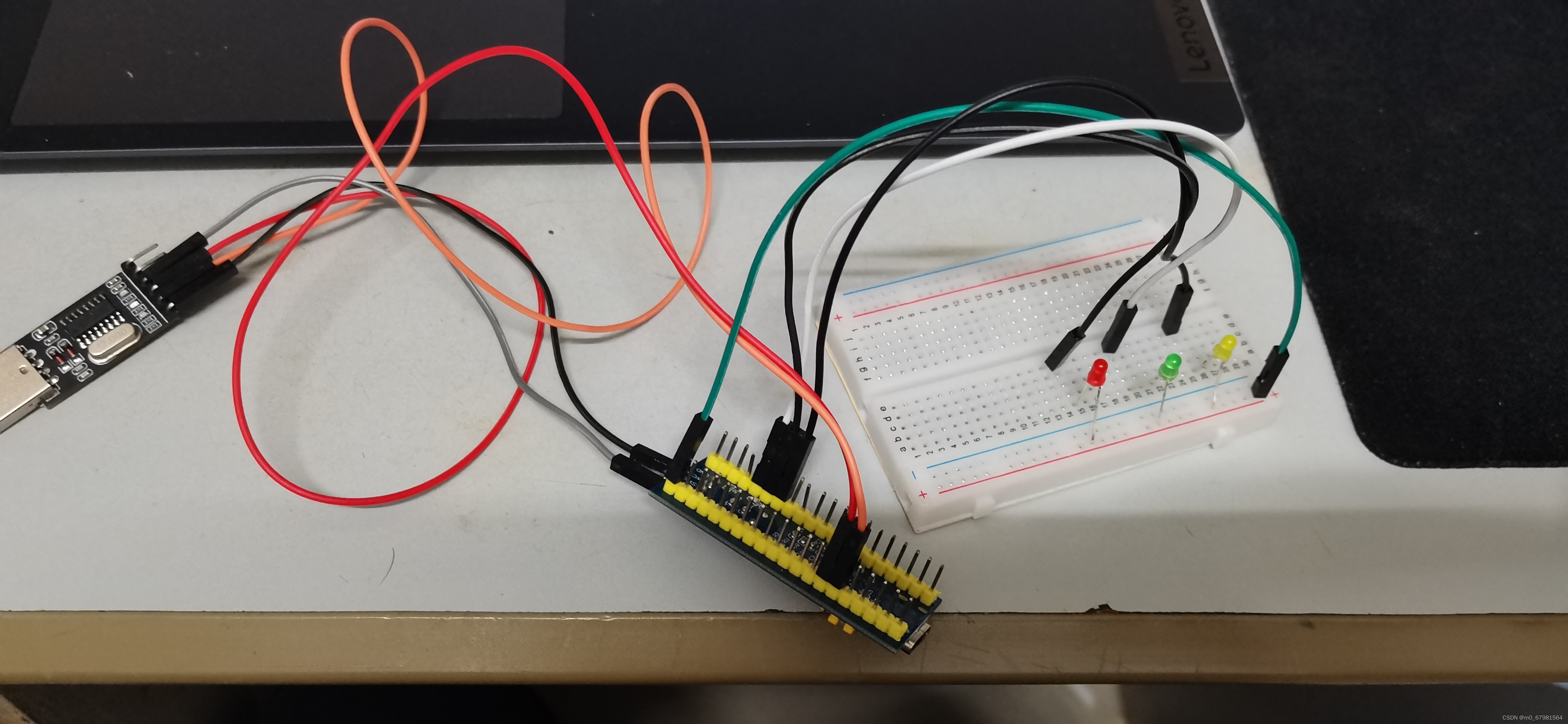
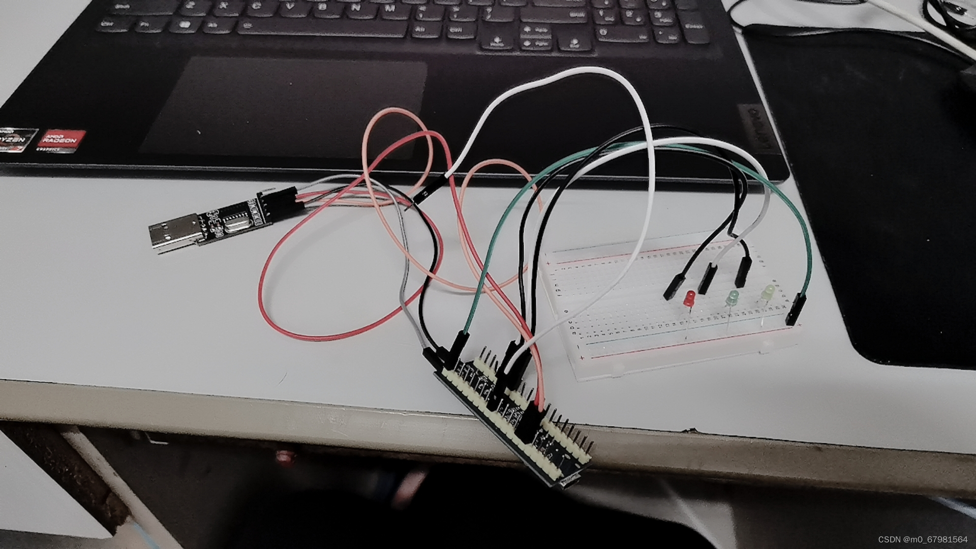
1. Line connection

PA0—-Red
PA1—-yellow
PA2—-green
PB5 is used as an interrupt trigger.
The physical connection is as shown below:
2. The effect diagram is as follows
Running lights and interruptions
3. Experimental experience
This experiment gave me a preliminary understanding of the use of the hal library, and preliminary learning of the process of using STM32CubeMX to create related projects. In fact, it has similarities with the register-based and standard library-based development methods. I am familiar with the hal library. Using it can effectively improve our development efficiency and reduce code writing. At the same time, a preliminary understanding of interruptions was obtained.