Experimental tasks:
Understand the serial port protocol and RS-232 standard, as well as the difference between RS232 level and TTL level; understand the working principle of the “USB/TTL to 232” module (taking the CH340 chip module as an example). Use the HAL library (or standard library) method to set the USART1 baud rate to 115200, 1 stop bit, and no parity bit. Use interrupt mode and DMA mode to complete the following tasks:
The STM32 system continuously sends “hello windows!” to the host computer (win10); when the host computer sends the character “stop” to stm32, stm32 pauses sending “hello windows!”; after sending a character “start”, stm32 continues to send; after Without an oscilloscope, you can use Keil’s software simulation logic analyzer function to observe the serial port output waveform, analyze whether the timing status is correct, and calculate the actual baud rate.
1. Serial communication principle and interrupt principle
2. Create MDK (keil5) project
1.Project structure
①.USER
②.Hardware
③.Delay
2.Basic settings
3. Specific implementation
1: Serial protocol
Serial Communication is a very commonly used serial communication method between devices. Because it is simple and convenient, most electronic devices support this communication method. Electronic engineers often use this communication method to output debugging when debugging equipment. information.
In computer science, most complex problems can be simplified through layers. For example, the chip is divided into the core layer and on-chip peripherals; the STM32 standard library is the software layer between the registers and user code. We also understand the communication protocol in a layered manner. The most basic thing is to divide it into the physical layer and the protocol layer.
2: The RS-232 standard interface (also known as EIA RS-232) is one of the commonly used serial communication interface standards. It is jointly developed by the Electronic Industries Association (EIA), Bell Systems, modem manufacturers and computer terminal manufacturers. Jointly formulated in 1970, its full name is “Technical Standard for Serial Binary Data Exchange Interface between Data Terminal Equipment (DTE) and Data Communications Equipment (DCE)”.
TL level standard
The output low level of TTL devices should be less than 0.8V, and the high level should be greater than 2.4V. Input, if it is lower than 1.2V, it is considered to be 0, and if it is higher than 2.0, it is considered to be 1. Therefore, the low-level noise margin of the TTL level input is only (0.8-0)/2=0.4V, and the high-level noise margin is (5-2.4)/2=1.3V.
RS232 standard
On the TXD and RXD data lines:
(1) Logic 1 is a voltage of -3~-15V
(2) Logic 0 is a voltage of 3~15V
On control lines such as RTS, CTS, DSR, DTR and DCD:
(1) The signal is valid (ON state) with a voltage of 3~15V
(2) The signal is invalid (OFF state) with a voltage of -3~-15V
This is specified by the communication protocol RS-232.
RS-232: Standard serial port, the most commonly used serial communication interface. There are three types (A, B and C), which use different voltages to indicate on and off. The most widely used one is RS-232C, which defines the mark(on) bit voltage to be between -3V and -12V, and the space(off) bit voltage to be between +3V and +12V. The maximum transmission distance is about 15 meters, and the maximum speed is 20kb/s. RS-232 is designed for point-to-point (that is, only one pair of receiving and transmitting devices) communication, and its driver load is 3~7kΩ. So RS-232 is suitable for communication between local devices.
3: USB/TTL to 232″ module
USB to serial port converts the computer USB interface to a physical serial port. You can add a serial port to a computer or other USB host that does not have a serial port. Using a USB-to-serial port device is equivalent to turning a traditional serial port device into a plug-and-play USB device.
The implementation of USB virtual serial port depends on the USB to serial port driver on the system, which is generally provided directly by the manufacturer. You can also use the CDC class serial port driver that comes with the operating system. The driver is mainly divided into two functions. One is to register the USB device driver to complete the control and data communication of the USB device. The other is to register the serial port driver to provide corresponding implementation methods for the serial port application layer.
Experimental tools:
(1) Software
KEIL5
(2)Hardware
The smallest core board of STM32F103C8T6
dupont line
USB to TTL module
accomplish
Set a status flag S, which defaults to 0, and wait for the appearance of the header (the header here sets a character by itself).
When it is detected that a received character matches the header character we specified, the flag bit S is set to 1, and the subsequent data starts to be received until a character is read that matches the first end bit we specified. Then set the flag bit S to 2, and no longer receive data, just wait for the character to match the second end bit, and set the status bit S to 0.
Here, the dual end flag is set. We can also set an end flag, so that the value of S only needs to be converted between 0 or 1, and the principle remains unchanged.
Create keil5 project

USER
Store the main.c file and the configuration file of the standard library
②.Hardware
Stores serial port trigger interrupts and some functions that utilize serial port communication
③.Delay
Store the delay function for us to call, which will be used later when using the microcontroller to send messages in a loop
Some basic settings


Experimental implementation
Configure RCC
 RCC_APB2PeriphClockCmd(RCC_APB2Periph_USART1,ENABLE);//Open the clock of the serial port
RCC_APB2PeriphClockCmd(RCC_APB2Periph_GPIOA,ENABLE); //Turn on the clocks of PA9 and PA10
Initialize GPIO port
GPIO_InitTypeDef GPIO_InitStruct;
//PA9 pin (corresponding to serial port sending function)
GPIO_InitStruct.GPIO_Mode = GPIO_Mode_AF_PP; //The TX pin is the output pin controlled by the USART peripheral, so the push-pull output must be multiplexed
GPIO_InitStruct.GPIO_Pin = GPIO_Pin_9;
GPIO_InitStruct.GPIO_Speed = GPIO_Speed_50MHz;
GPIO_Init(GPIOA, & amp;GPIO_InitStruct);
//PA10 pin (corresponding to serial port receiving function)
GPIO_InitStruct.GPIO_Mode = GPIO_Mode_IN_FLOATING;
GPIO_InitStruct.GPIO_Pin = GPIO_Pin_10;
GPIO_InitStruct.GPIO_Speed = GPIO_Speed_50MHz;
GPIO_Init(GPIOA, & amp;GPIO_InitStruct);
Initialize UART
 USART_InitTypeDef USART_InitStruct;
USART_InitStruct.USART_BaudRate = 9600;//Set the baud rate
USART_InitStruct.USART_HardwareFlowControl =USART_HardwareFlowControl_None; //Hardware flow control
USART_InitStruct.USART_Mode = USART_Mode_Tx | USART_Mode_Rx;//If you only need to send, you only need TX, if you need to receive, you can use RX
USART_InitStruct.USART_Parity = USART_Parity_No;//No check digit
USART_InitStruct.USART_StopBits = USART_StopBits_1;//1 stop bit
USART_InitStruct.USART_WordLength = USART_WordLength_8b;//Select 8-bit word length
USART_Init(USART1, & amp;USART_InitStruct);
Interrupt function
#include "stm32f10x.h" // Device header
#include "stdio.h"
#include <stdio.h>
#include <string.h>

uint8_t Serial_RxFlag;//Define a receive flag bit
char Serial_RxPacket[100];//Define a global char array. The range can be larger. This array will be externed in the header file for easy use in the main function.

void Serial_Init(void)
{<!-- -->
GPIO_InitTypeDef GPIO_InitStruct;
USART_InitTypeDef USART_InitStruct;
NVIC_InitTypeDef NVIC_InitStructure;
\t
//The first step is to start the clock
RCC_APB2PeriphClockCmd(RCC_APB2Periph_USART1,ENABLE);
RCC_APB2PeriphClockCmd(RCC_APB2Periph_GPIOA,ENABLE); //Turn on the clocks of PA9 and PA10
\t
//Second initialization pin
\t
//PA9 pin
GPIO_InitStruct.GPIO_Mode = GPIO_Mode_AF_PP; //The TX pin is the output pin controlled by the USART peripheral, so the push-pull output must be multiplexed
GPIO_InitStruct.GPIO_Pin = GPIO_Pin_9;
GPIO_InitStruct.GPIO_Speed = GPIO_Speed_50MHz;
GPIO_Init(GPIOA, & amp;GPIO_InitStruct);
//PA10 pin
GPIO_InitStruct.GPIO_Mode = GPIO_Mode_IN_FLOATING;
GPIO_InitStruct.GPIO_Pin = GPIO_Pin_10;
GPIO_InitStruct.GPIO_Speed = GPIO_Speed_50MHz;
GPIO_Init(GPIOA, & amp;GPIO_InitStruct);
\t
//The third step initializes USART

USART_InitStruct.USART_BaudRate = 9600;//Set the baud rate
USART_InitStruct.USART_HardwareFlowControl =USART_HardwareFlowControl_None; //Hardware flow control
USART_InitStruct.USART_Mode = USART_Mode_Tx | USART_Mode_Rx;//If you only need to send, you only need TX, if you need to receive, you can use RX
USART_InitStruct.USART_Parity = USART_Parity_No;//No check digit
USART_InitStruct.USART_StopBits = USART_StopBits_1;//1 stop bit
USART_InitStruct.USART_WordLength = USART_WordLength_8b;
USART_Init(USART1, & amp;USART_InitStruct);
\t
//The fourth step turns on interrupt
USART_ITConfig(USART1,USART_IT_RXNE,ENABLE);
NVIC_PriorityGroupConfig(NVIC_PriorityGroup_2);
NVIC_InitStructure.NVIC_IRQChannel = USART1_IRQn;
NVIC_InitStructure.NVIC_IRQChannelCmd = ENABLE;
NVIC_InitStructure.NVIC_IRQChannelPreemptionPriority = 1;
NVIC_InitStructure.NVIC_IRQChannelSubPriority = 1;
NVIC_Init( & amp;NVIC_InitStructure);
\t
\t
\t
USART_Cmd(USART1,ENABLE);//Enable USART peripherals
}


uint8_t Serial_GetRxFlag(void) //Used to return a flag indicating whether a string has been received
{<!-- -->
if(Serial_RxFlag == 1)
{<!-- -->
Serial_RxFlag = 0;
return 1;
}
return 0;
}


void Serial_SendByte(uint8_t Byte)
{<!-- -->
USART_SendData(USART1,Byte);//Call this library function to write the byte variable to TDR
//You need to wait for a while until the TDR data is moved to the shift register before we can proceed with the next output.
while(USART_GetFlagStatus(USART1,USART_FLAG_TXE)==RESET);
//TXE send data register empty flag, this flag will be cleared automatically, we do not need to clear it manually
\t
}

void Serial_SendString(char *String) // A string sending function
{<!-- -->
uint8_t i;
for(i=0;String[i]!=0;i + + )
{<!-- -->
Serial_SendByte(String[i]);
}
\t
}

//interrupt function
void USART1_IRQHandler()
{<!-- -->
static u8 pRxpacket = 0; // Define an Rxpacket array subscript
static u8 Rxstate = 0; //Define flag bit
\t
if(USART_GetITStatus(USART1,USART_IT_RXNE)==SET)
{<!-- -->
u8 RxData = USART_ReceiveData(USART1);
\t\t
if(Rxstate==0)
{<!-- -->
if(RxData=='[')//The starting identifier is'['
{<!-- -->
memset(Serial_RxPacket,'\0',sizeof(Serial_RxPacket));//Clear this array
pRxpacket = 0;//The array subscript used to assign values to the array must be set to 0 before the flag Rxstate changes.
Rxstate=1;
}
}
else if(Rxstate==1)
{<!-- -->
if(RxData==']')//The end identifier is']'
{<!-- -->
Rxstate=0;
Serial_RxFlag=1;//Set RxFlag to 1 to prove that an entire string has been fetched, and this string can be read in the main function
}
else
{<!-- -->
Serial_RxPacket[pRxpacket] = RxData;
pRxpacket + + ;
}
}
USART_ClearITPendingBit(USART1,USART_IT_RXNE);
}
}
Main function execution, judgment and response
#include "stm32f10x.h" // Device header
#include <stdio.h>
#include "Serial.h"
#include "Delay.h"
#include <string.h>

int main(void)
{<!-- -->
Serial_Init();
while(1)
{<!-- -->
if(Serial_GetRxFlag()==1)//If the acceptance flag position is 1, that is, a string is successfully read
{<!-- -->
if(strcmp(Serial_RxPacket,"go stm32!")==0)//The string here can be set as desired.
{<!-- -->
while(1)
{<!-- -->
Serial_SendString("hello windows!\
");
Delay_ms(800);
\t\t\t\t\t
if(strcmp(Serial_RxPacket,"stop stm32!")==0)
{<!-- -->
break;
}
}
\t\t\t\t
}
}
\t\t
}
}
Header files and tool files
Delay.c
#include "stm32f10x.h"

/**
  * @brief Microsecond delay
  * @param xus Delay length, range: 0~233015
  * @retval None
  */
void Delay_us(uint32_t xus)
{<!-- -->
SysTick->LOAD = 72 * xus; //Set the timer reload value
SysTick->VAL = 0x00; //Clear the current count value
SysTick->CTRL = 0x00000005; //Set the clock source to HCLK and start the timer
while(!(SysTick->CTRL & amp; 0x00010000)); //Wait for the count to 0
SysTick->CTRL = 0x00000004; //Close the timer
}

/**
  * @brief millisecond delay
  * @param xms Delay length, range: 0~4294967295
  * @retval None
  */
void Delay_ms(uint32_t xms)
{<!-- -->
while(xms--)
{<!-- -->
Delay_us(1000);
}
}

/**
  * @brief second level delay
  * @param xs delay length, range: 0~4294967295
  * @retval None
  */
void Delay_s(uint32_t xs)
{<!-- -->
while(xs--)
{<!-- -->
Delay_ms(1000);
}
}
Delay.h
#ifndef __DELAY_H
#define __DELAY_H

void Delay_us(uint32_t us);
void Delay_ms(uint32_t ms);
void Delay_s(uint32_t s);

#endif
Serial.h
#ifndef _Serial_H
#define _Serial_H
extern char Serial_RxPacket[];
void Serial_Init(void);
void Serial_SendByte(uint8_t Byte);
void Serial_SendString(char *String);
uint8_t Serial_GetRxFlag(void);
#include <stdio.h>
#endif
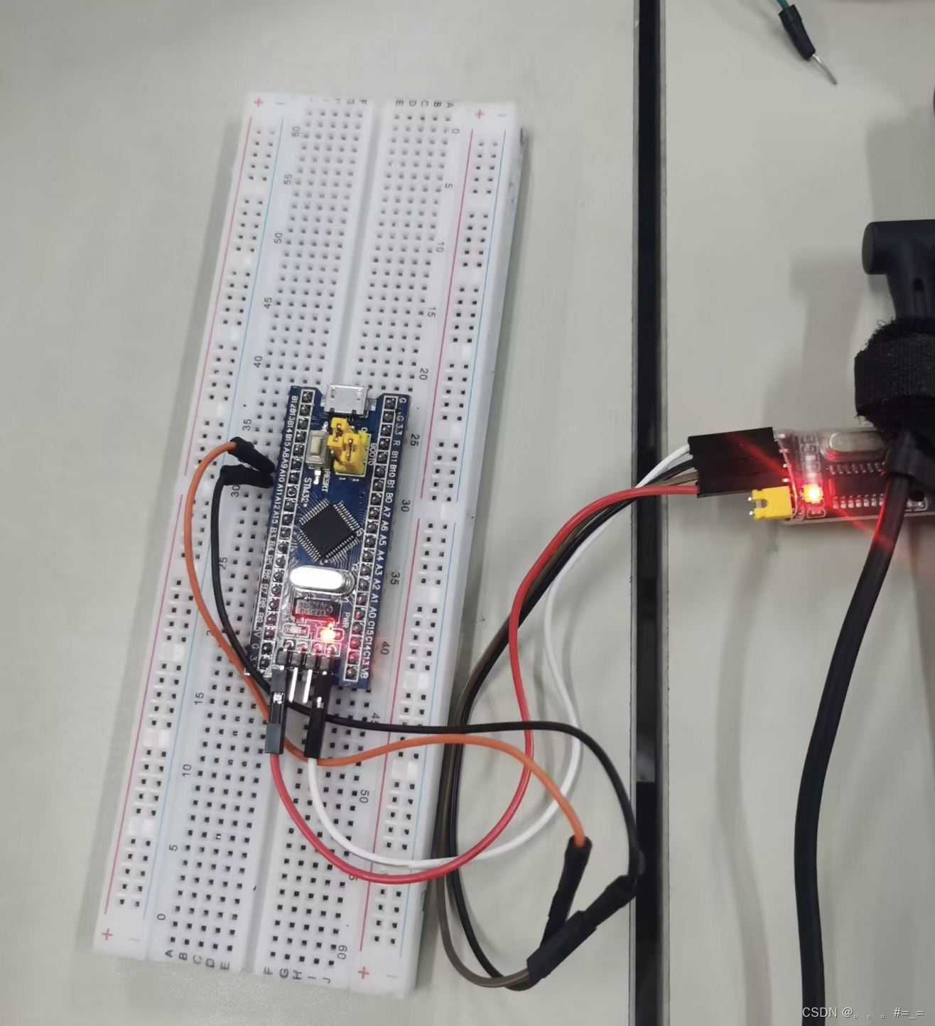
Physical display of wiring
Experimental effect

Experiment summary
During the experiment, I discovered the following points worth noting. When initializing peripherals, as long as it involves calling the macro definition in the standard library to generate a structure variable, it must be written at the front, otherwise when compiling An error will be reported. The array subscript pRxstate used to assign values to the array must be set to 0 before the flag Rxstate changes. Otherwise, the subscript cannot be returned to zero in time during operation. The experiment was still very difficult for me, and for those who were not very proficient in the C language, the progress was slow, but fortunately it was finally completed.