article:
- Three–1. Getting to know Three and basic front-end scene construction (source code at the end)
- Three–2. Strengthen the understanding of three-dimensional space
- Three–three, animation execution, canvas size, rendering frame rate and camera adaptation experience
- Three–four, geometry, high-gloss network material, jagged blur, and the use of GUI libraries
- Three–five, point-line model objects, triangle concept, geometry vertex position, vertex index, normal, and rotation, scaling and translation of geometry
About Geometry BufferGeomety
Sphere SphereGeometry, cube BoxGeometry, etc. are all part of the geometry
Geometry vertex position data and point model
bottom layer, look down
Buffer type geometry BufferGeometry
If you want to create irregular geometric shapes, you can customize it through BufferGeometry, which is the so-called vertex data
Example: Create an empty geometry object
const geometry = new Three. BufferGeometry();
Use the typed array Float32Array in js to create xyz coordinate data to represent vertex coordinates
//Typed array to create vertex data
const vertices = new Float32Array([
    0, 0, 0, //vertex 1 coordinates
    50, 0, 0, //vertex 2 coordinates
    0, 100, 0, //vertex 3 coordinates
    0, 0, 10, //vertex 4 coordinates
    0, 0, 100, //vertex 5 coordinates
    50, 0, 10, //vertex 6 coordinates
]);
The buffer object BufferAttribute represents the geometry vertex data
// create attribute buffer object
//3 as a group, representing the xyz coordinates of a vertex
const attribute = new THREE. BufferAttribute(vertices, 3);
Set geometry vertex position .attributes.position
geometry.attributes.position = attribute;
 const geometry = new THREE. BufferGeometry();
    const vertices = new Float32Array([
      0, 0, 0, //vertex 1 coordinates
      50, 0, 0, //vertex 2 coordinates
      0, 100, 0, //vertex 3 coordinates
      0, 0, 10, //vertex 4 coordinates
      0, 0, 100, //vertex 5 coordinates
      50, 0, 10, //vertex 6 coordinates
    ])
    const attribute = new THREE. BufferAttribute(vertices, 3);
    geometry.attributes.position = attribute;
    // material
    material = new THREE. MeshBasicMaterial({<!-- -->
      color: 0x00ffff,
      transparent: true, // turn on transparency
      // opacity: 0.5, //Set transparency
      side: THREE.DoubleSide, //Visible on both sides
      shininess: 500,
    });
    mesh = new THREE. Mesh(geometry, material);
    mesh.position.set(0, 0, 0);
    scene. add(mesh);

Point model Points
As the name implies, it is to replace the Mesh surface material with points
For example:
// point rendering mode
const material = new THREE. PointsMaterial({<!-- -->
    color: 0x00ffff,
    size: 10.0 //point object pixel size
});
Convert geometry to point model
const points = new THREE.Points(geometry, material); //point model object

Lineline model object
The line model is to connect from the first point to the last point and form lines in turn
Line material object LineBasicMaterial
We keep three points here to form a triangle
const vertices = new Float32Array([
    0, 0, 0,
    50, 0, 0,
    0, 100, 0,
]);
// line material object
const material = new THREE.LineBasicMaterial({<!-- -->
    color: 0x00ffff //line color
});
// create line model object
const line = new THREE. Line(geometry, material);

Here you will find that the last line is not connected to show the closed effect, and then look down.
Line model LineLoop
to close lines
// closed line
const line = new THREE. LineLoop(geometry, material);

Non-continuous line LineSegments
//non-continuous lines
const line = new THREE. LineSegments(geometry, material);

Network model (triangle concept)
The network model Mesh is composed of one or more triangles. Use the mesh model Mesh to render the geometry, that is, all the coordinates of the vertices of the geometry are grouped into a group to form a triangle, and multiple groups of vertices form multiple triangles, which can be used to simulate the surface of the object.
Visible on both sides
what has happened before and let both sides see
const material = new THREE.MeshBasicMaterial({<!-- -->
    color: 0x00ffff , //material color
    side: THREE.FrontSide, //Only the front side is visible by default
});
const material = new THREE.MeshBasicMaterial({<!-- -->
    side: THREE.DoubleSide, //Visible on both sides
});
const material = new THREE.MeshBasicMaterial({<!-- -->
    side: THREE.BackSide, //Set only the back side is visible
});
Constructing rectangular planar geometry
Regarding where the coordinate points should start, here the front is connected counterclockwise, and the back is connected clockwise, counterclockwise (from bottom to top, from right to left)
So the coordinates to generate a plane square are
 const geometry = new THREE. BufferGeometry();
    const vertices = new Float32Array([
      0, 0, 0,
      80, 0, 0,
      80, 80, 0,

      0, 0, 0,
      80, 80, 0,
      0, 80, 0,
    ]);
    const attribute = new THREE. BufferAttribute(vertices, 3);

    geometry.attributes.position = attribute;
    // material
    material = new THREE.LineBasicMaterial({<!-- -->
      color: 0x00ffff,
    });
    // Change to closed line effect
    mesh = new THREE. LineLoop(geometry, material);
    mesh.position.set(0, 0, 0);
    scene. add(mesh);
Let’s add a coordinate system to the scene to see
 const axesHelper = new THREE.AxesHelper(150);
    scene. add(axesHelper);
[External link picture transfer failed, the source site may have an anti-leeching mechanism, it is recommended to save the picture and upload it directly (img-OgQ4Ym4P-1683602169841)(img/Three05Img/sbx.png)]
Geometry vertex index data
To reduce the number of vertex coordinates of a triangle, you can use the geometry vertex index geometry.index to achieve
const vertices = new Float32Array([
    0, 0, 0, //vertex 1 coordinates
    80, 0, 0, //vertex 2 coordinates
    80, 80, 0, //vertex 3 coordinates
    0, 0, 0, //The coordinates of vertex 4 are the same as the position of vertex 1
    80, 80, 0, //The coordinates of vertex 5 are the same as the position of vertex 3
    0, 80, 0, //vertex 6 coordinates
]);
If there are duplicates, the duplicate vertices can be deleted
const vertices = new Float32Array([
    0, 0, 0, //vertex 1 coordinates
    80, 0, 0, //vertex 2 coordinates
    80, 80, 0, //vertex 3 coordinates
    0, 80, 0, //vertex 4 coordinates
   ]);

Use BufferAttribute to create the data of vertex index .index
Create the data of the vertex index .index through the typed array Unit16Array in js
const indexes = new Uint16Array([
    // The following index values correspond to the vertex coordinates in the vertex position data
    0, 1, 2, 0, 2, 3,
])
Use the buffer object BufferAttribute to represent the geometry vertex index .index data
geometry.index = new THREE.BufferAttribute(indexes, 1); // 1 as a group
The effect is as follows:

vertex normal data
A new vertex data, vertex normal (normal vector) data geometry.attributes.normal
If you change the MeshBasicMaterial material to the MeshLambertMaterial material, the rectangular plane here cannot be rendered normally, because the geometry must define the vertex normal< /strong>Data.
code:
 const geometry = new THREE. BufferGeometry();
    const vertices = new Float32Array([0, 0, 0, 80, 0, 0, 80, 80, 0, 0, 80, 0]);

    const indexes = new Uint16Array([
      // The following index values correspond to the vertex coordinates in the vertex position data
      0, 1, 2, 0, 2, 3,
    ]);
    const attribute = new THREE. BufferAttribute(vertices, 3);
    geometry.index = new THREE.BufferAttribute(indexes, 1); //1 for a group
    geometry.attributes.position = attribute;
    // material
    material = new THREE. MeshBasicMaterial({<!-- -->
      color: 0x00ffff,
      transparent: true, // turn on transparency
      // opacity: 0.5, //Set transparency
      side: THREE.DoubleSide, //Visible on both sides
    });
    mesh = new THREE. Mesh(geometry, material);
    mesh.position.set(0, 0, 0);
    scene. add(mesh);

After changing the material to MeshLambertMaterial

Normal of rectangular plane geometry — no vertex index
The normal in Three.js is defined by vertices. By default, each vertex has a normal data, just like each vertex has a position data.
// rectangular plane, no index, two triangles, 6 vertices
// The normal data of each vertex corresponds to the vertex position data one by one
const normals = new Float32Array([
    0, 0, 1, //vertex 1 normal ( normal vector )
    0, 0, 1, //vertex 2 normal
    0, 0, 1, //vertex 3 normal
    0, 0, 1, //vertex 4 normal
    0, 0, 1, //vertex 5 normal
    0, 0, 1, //vertex 6 normal
]);
// Set the vertex normal attribute of the geometry.attributes.normal
geometry.attributes.normal = new THREE.BufferAttribute(normals, 3);
Effect:

With vertex index
// Rectangular plane with index, two triangles, 2 vertices overlap, 4 vertices
// The normal data of each vertex corresponds to the vertex position data one by one
const normals = new Float32Array([
    0, 0, 1, //vertex 1 normal ( normal vector )
    0, 0, 1, //vertex 2 normal
    0, 0, 1, //vertex 3 normal
    0, 0, 1, //vertex 4 normal
]);
// Set the vertex normal attribute of the geometry.attributes.normal
geometry.attributes.normal = new THREE.BufferAttribute(normals, 3);
View three.js built-in geometry vertices
View geometry vertex position and index data
If I want to directly know the fixed-point position and index data of the rectangular plane, then I can use the property to print and view it in the console
// const geometry = new THREE.PlaneGeometry(100,50); //rectangular plane geometry
const geometry = new THREE.BoxGeometry(100,100,100); //cuboid

console.log('geometry', geometry);
console.log('vertex position data', geometry.attributes.position);
console.log('vertex index data', geometry.index);

Material property wireframe
const material = new THREE.MeshLambertMaterial({<!-- -->
    color: 0x00ffff,
    wireframe: true, // line mode renders the triangle data corresponding to the mesh
});

Geometry Subdivision
Rectangular planar geometry requires at least two triangles to be stitched together. The parameters 3 and 4 in the rectangular geometry PlaneGeometry represent the number of subdivisions, and the default value is 1,1
 //The parameters 3,4 of the rectangular geometry PlaneGeometry represent the number of subdivisions, the default is 1,1
const geometry = new THREE. PlaneGeometry(100,50,1,1);
// A rectangle is divided into two, and there are two triangles on each rectangle, that is, four
const geometry = new THREE. PlaneGeometry(100,50,2,1);
// Divide a rectangle into 4 parts, each rectangle has 2 triangles, a total of 8 triangles
const geometry = new THREE. PlaneGeometry(100,50,2,2);
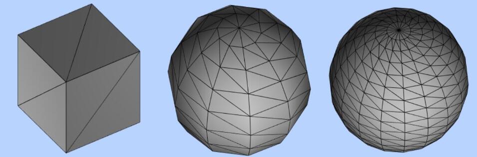
Number of subdivisions of a sphere SphereGeometry
Parameters 2 and 3 represent the number of subdivisions in the two directions of width and height respectively. The default is 32 and 61. The specific situation depends on the version
For example:
const geometry = new THREE. SphereGeometry(100, 10, 10);

The more subdivisions, the rounder the sphere will be

About the number and performance of triangles
For a surface, the higher the number of subdivisions, the smoother the surface, but the higher the number of triangles and vertices.
The number of geometric triangles or vertices directly affects the rendering performance of Three.js. In the case of not affecting the rendering effect, the less the better. ,
Rotate, scale, translate geometry
BufferGeinetry geometry can be rotated, zoomed and translated through css3 attributes
Scale .scale(), translate .translate(), rotate rotateX, Y, Z()
// Length, width and height scaling
geometry. scale(2, 2, 2);
// x-axis offset by 50px
geometry. translate(50, 0, 0);
// The geometry is rotated 45 degrees around the x-axis
geometry.rotateX(Math.PI / 4);

Center .center()
If the geometry has been offset, then execute ceenter to re-coordinate with the origin of the coordinates
geometry. center();
